IED
V0
0683
I
Phase A
I
Phase B
I
Phase C
I
Neutral
Phase A
Phase B
Phase C
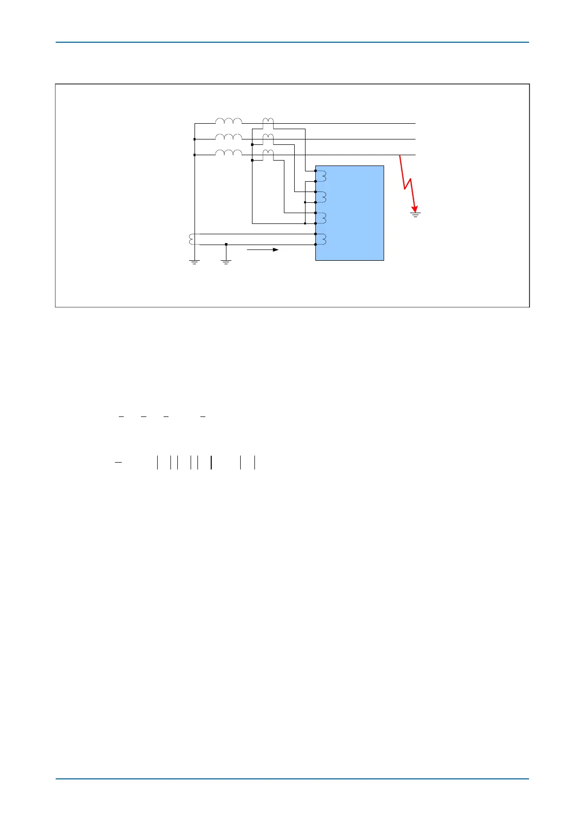
Line CTs 1000:1
Neutral CT 200:1
I
N
Figure 97: Low Impedance REF Scaling Factor
Another advantage of Low Impedance REF pr
otection is that you can use a neutral CT with a lower ratio than the
line CTs in order to provide better earth fault sensitivity. In the bias calculation, the device applies a scaling factor
to the neutral current. This scaling factor is as follows:
Scaling factor = K = Neutral CT ratio / Line CT ratio
This results in the following differential and bias current equations:
I I I I KI
diff
A B C N
= + +
( )
+
I I I I K I
bias A B C N
=
+
{ }
1
2
max , ,
4.2.3 PARAMETER CALCULATIONS
Consider a solidly earthed 90 MVA transformer with a REF-protected star winding. Assume line CTS with a ratio of
400:1.
Is1 is set to 10% of the winding nominal curr
ent:
= (0.1 x 90 x 10
6
) / (
Ö
3 x 132 x 10
3
)
= 39 Amps primary
= 39/400 = 0.0975 Amps secondary (approx 0.1 A)
Is2 is set to the rated current of the transformer:
= 90 x 10
6
/ (
Ö
3 x 132 x 10
3
)
= 390 Amps primary
= 390/400 = 0.975 Amps secondary (approx 1 A)
Set K1 to 0% and K2 to 150%
Chapter 7 - Restricted Earth Fault Protection P14x
176 P14xEd1-TM-EN-1
 Loading...


