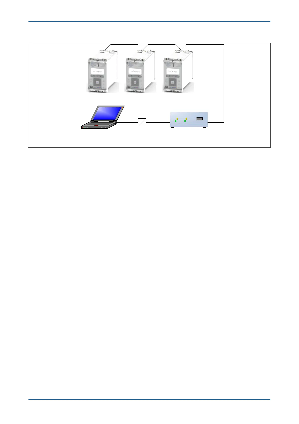
IED IED IED
K-BusRS232
KITZ protocol converterRS232-USB converterComputer
V0
1001
Figure 219: Remote communication using K-bus
Fibre Connection
Some models hav
e an optional fibre optic communications port fitted (on a separate communications board). The
communications port to be used is selected by setting the Physical Link cell in the COMMUNICATIONS column, the
values being Copper or K-Bus for the RS485/K-bus port and Fibre Optic for the fibre optic port.
5.2.10.2 CHECK LOGICAL CONNECTIVITY
The logical connectivity depends on the chosen data protocol, but the principles of testing remain the same for all
protocol v
ariants:
1. Ensure that the communications baud rate and parity settings in the application software are set the same
as those on the protocol converter.
2. For Courier models, ensure that you have set the correct RP1 address
3. Check that communications can be established with this IED using the portable PC/Master Station.
5.2.11 TEST SERIAL COMMUNICATION PORT RP2
RP2 is an optional second serial port board providing additional serial connectivity. It provides two 9-pin D-type
serial por
t connector
s SK4 and SK5. Both ports are configured as DTE (Date Terminal Equipment) ports. That means
they can be connected to communications equipment such as a modem with a straight-through cable.
SK4 can be configured as an EIA(RS232), EIA(RS485), or K-Bus connection for Courier protocol only, whilst SK5 is
fixed to EIA(RS)232 for InterMiCOM signalling only.
It is not the intention of this test to verify the operation of the complete communication link between the IED and
the remote location, just the IED's rear communication port and, if applicable, the protocol converter.
The only checks that need to be made are as follows:
1. Set the RP2 Port Config cell in the COMMUNICATIONS column to the required physical protocol; (K-Bus,
EIA(RS)485, or EIA(RS)232.
2. Set the IED's Courier address to the correct value (it must be between 1 and 254).
5.2.12 TEST ETHERNET COMMUNICATION
For products that employ Ethernet communications, we recommend that testing be limited to a visual check that
the correct por
ts are fitted and that there is no sign of physical damage.
Chapter 21 - Commissioning Instructions P14x
502 P14xEd1-TM-EN-1
 Loading...


