16 LOAD BLINDERS
Load blinding is a mechanism, where protection elements are prevented from tripping under heavy load, but
healthy conditions. In the past this mechanism was mainly used for transmission systems and w
as rarely needed
at distribution voltage levels. In the last few years, however, distribution networks have become more subject to
periods of sustained heavy loads. This is due to a number of reasons, one of which is the increase of distributed
generation. For this reason, it has become very desirable to equip overcurrent protection, normally targeted at
distribution networks, with load blinding functionality.
Load blinders work by measuring, not only the system current levels, but also the system voltage levels and
making tripping decisions based on analysis of both of these measurements. This is known as Impedance
measurement.
When the measured current is higher than normal, this can be caused by one of two things; either a fault or a
heavy load. If the cause is a fault, the system voltage level will reduce significantly. However, if the cause is a
heavy, but healthy load, the voltage will not decrease significantly. Therefore, by measuring the both the system
voltage and currents, the protection can make a decision not to trip under heavy load conditions.
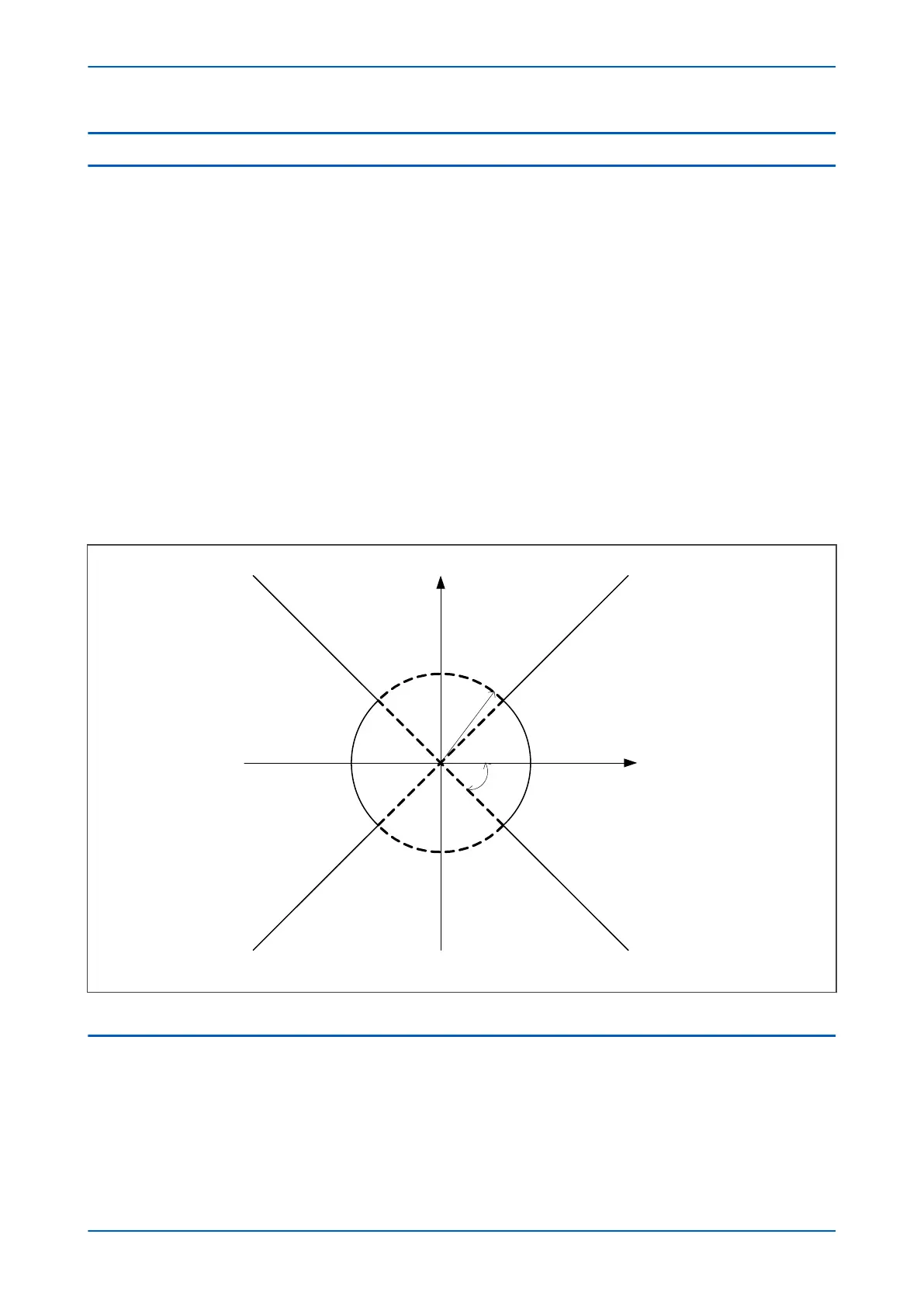
The principle of a load blinder is to configure a blinder envelope, which surrounds the expected worst case load
limits, and to block tripping for any impedance measured within this blinder region. Only fault impedance outside
the load area is allowed to cause a trip. It is possible to set the impedance and angle setting independently for the
forward and reverse regions in the Z plane.
V00645
Blind area
Operate area
Blind area
Operate area
Z
β
jX
R
Figure 78: Load blinder and angle
16.1 LOAD BLINDER IMPLEMENTATION
The Load blinder function is implemented in the OVER
CURRENT column of the relevant settings group, under the
sub-heading LOAD BLINDER.
The settings allow you to set the impedance and angle limits for both reverse and forward directions, the
undervoltage and negative sequence current thresholds for blocking the function, and the operation mode.
There are two modes of operation; single phase and three phase;
Chapter 6 - Current Protection Functions P14x
152 P14xEd1-TM-EN-1
 Loading...


