4 OVERFREQUENCY PROTECTION
An increased system frequency arises when the mechanical power input to a generator exceeds the electrical
power output
. This could happen, for instance, when there is a sudden loss of load due to tripping of an outgoing
feeder from the plant to a load centre. Under such conditions, the governor would normally respond quickly to
obtain a balance between the mechanical input and electrical output, thereby restoring normal frequency.
Overfrequency protection is required as a backup to cater for cases where the reaction of the control equipment is
too slow.
4.1 OVERFREQUENCY PROTECTION IMPLEMENTATION
The following settings are relevant for overfrequency:
● St
g (n) f+t Status: determines whether the stage is underfrequency, overfrequency, or disabled
● Stg (n) f+t Freq: defines the frequency pickup setting
● Stg (n) f+t Time: sets the time delay
Note:
This section refers to advanced frequency protection. The basic frequency protection works in a similar manner, but the
setting names and DDB signal names are different.
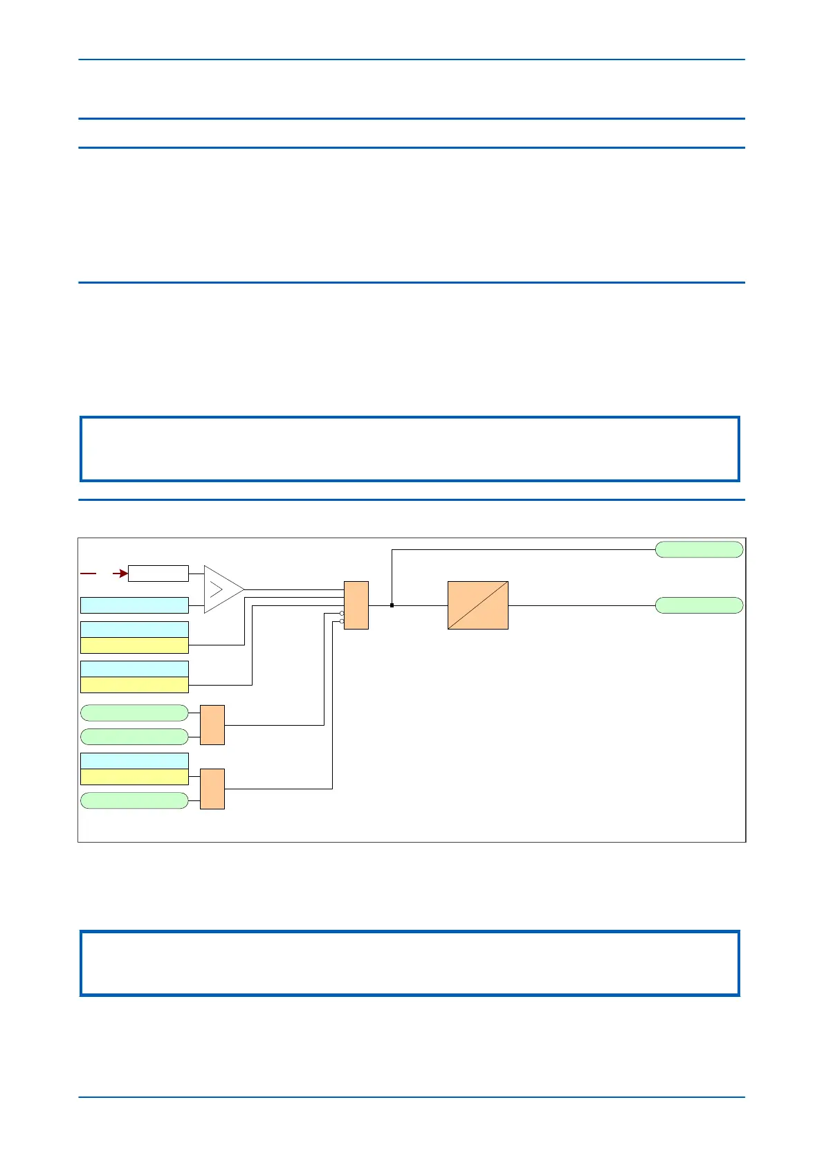
4.2 OVERFREQUENCY PROTECTION LOGIC
Stg 1 f+t Status
Stg1 f+t Trp
Stage 1
V00851
Freq
DT
Stg1 f+t Sta
&
Enabled
Over
Stg 1 f+t Freq
Adv Freq Inh
Freq Not Found
1
Averaging
V<B Status
Enabled
UV Block
1
Note : This diagram does not show all stages . Other stages follow similar principles.
Figure 127: Overfrequency logic (single stage)
If the frequency is above the setting and not blocked, the DT timer is started and after this has timed out, the trip is
produced. If the frequency cannot be determined, the function is blocked.
Note:
This section refers to advanced frequency protection. The basic frequency protection works in a similar manner, but the
setting names and DDB signal names are different.
Chapter 11 - Frequency Protection Functions P14x
240 P14xEd1-TM-EN-1
 Loading...


