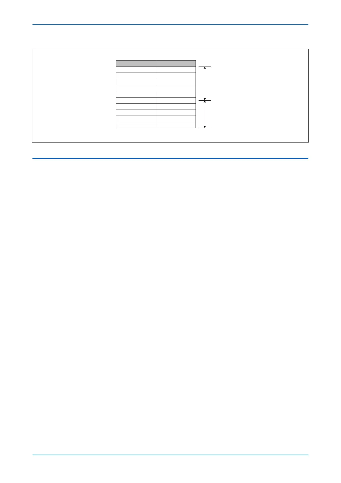
X in %
V0
0682
Idiff in %
10 0.58
100
90
80
70
60
50
40
30
20
57.74
46.77
36.95
28.29
20.00
14.43
9.24
5.20
2.31
59% of unprotected winding
41
% of unprotected winding
Figure 96: Percentage of winding protected
4.2 LOW IMPEDANCE REF PROTECTION APPLICATION
4.2.1 SETTING GUIDELINES FOR BIASED OPERATION
Two bias settings are provided in the REF characteristic. The K1 level of bias is applied up to through currents of
Is2, which is normally set to the rated curr
ent of the transformer
. K1 is normally be set to 0% to give optimum
sensitivity for internal faults. However, if any CT mismatch is present under normal conditions, then K1 may be
increased accordingly, to compensate. We recommend a setting of 20% in this case.
K2 bias is applied for through currents above Is2 and would typically be set to 150%.
According to ESI 48-3 1977, typical settings for the Is1 thresholds are 10-60% of the winding rated current when
solidly earthed and 10-25% of the minimum earth fault current for a fault at the transformer terminals when
resistance earthed.
4.2.2 LOW IMPEDANCE REF SCALING FACTOR
The three line CTs are connected to the three-phase CTs, and the neutral CT is connected to the neutral CT input.
These curr
ents ar
e then used internally to derive both a bias and a differential current quantity for use by the low
impedance REF protection. The advantage of this mode of connection is that the line and neutral CTs are not
differentially connected, so the neutral CT can also be used to provide the measurement for the Standby Earth
Fault Protection. Also, no external components such as stabilizing resistors or Metrosils are required.
P14x Chapter 7 - Restricted Earth Fault Protection
P14xEd1-TM-EN-1 175
 Loading...


