4-14
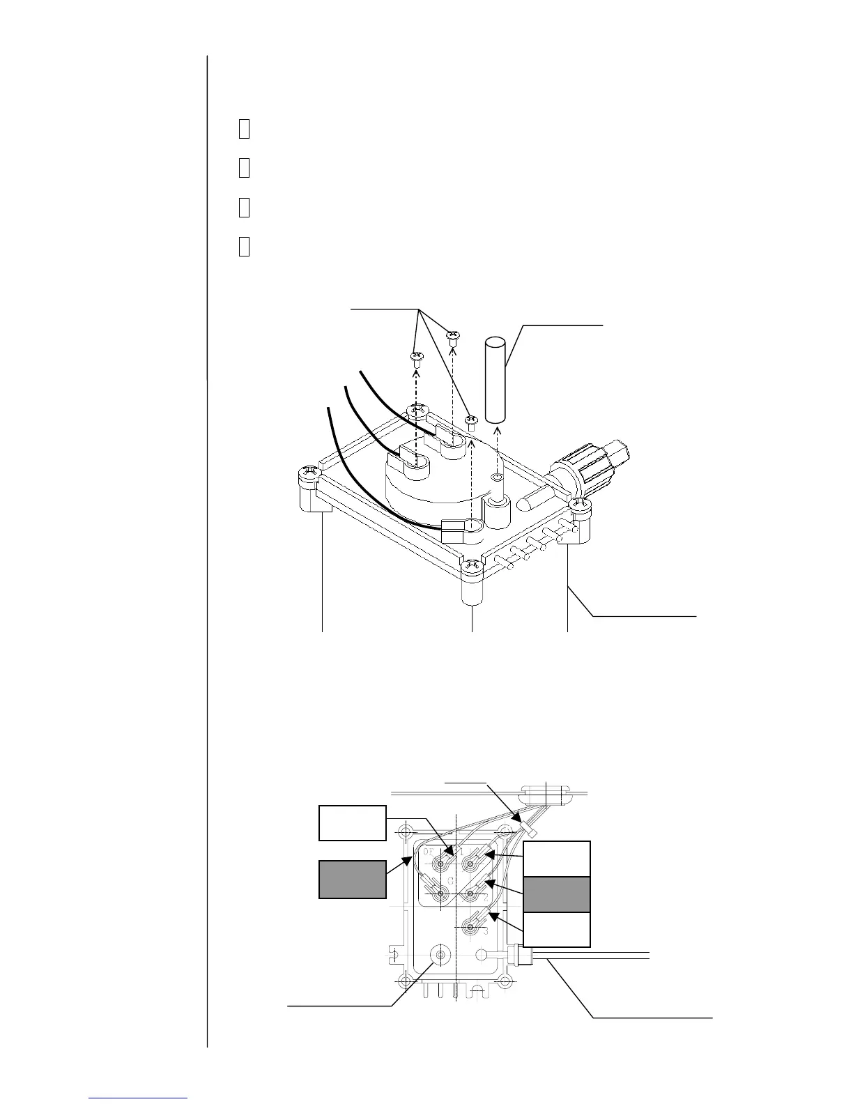
4.8 Circulation Unit Replacement Procedure
1 Perform “Ink drainage” and then “Pressure relief”.
2 Turn off the power supply.
3 Perform “4.1.3 Approach to the parts on the rear side of the equipment”.
4 Remove the wire connecting part screws (3 positions) of the liquid level
sensor in the main ink tank and the exhaust tube.
*) The wire connecting part of the liquid level sensor for the PXR-H is different
from PXR-D. There are five positions of the wire connecting part screws.
Fixing screw
Exhaust tube
Black (long)
White
Black (short)
Main ink tank
White
Overflow
Black
GND
黒
Bind
Recovery tube
 Loading...