6-13
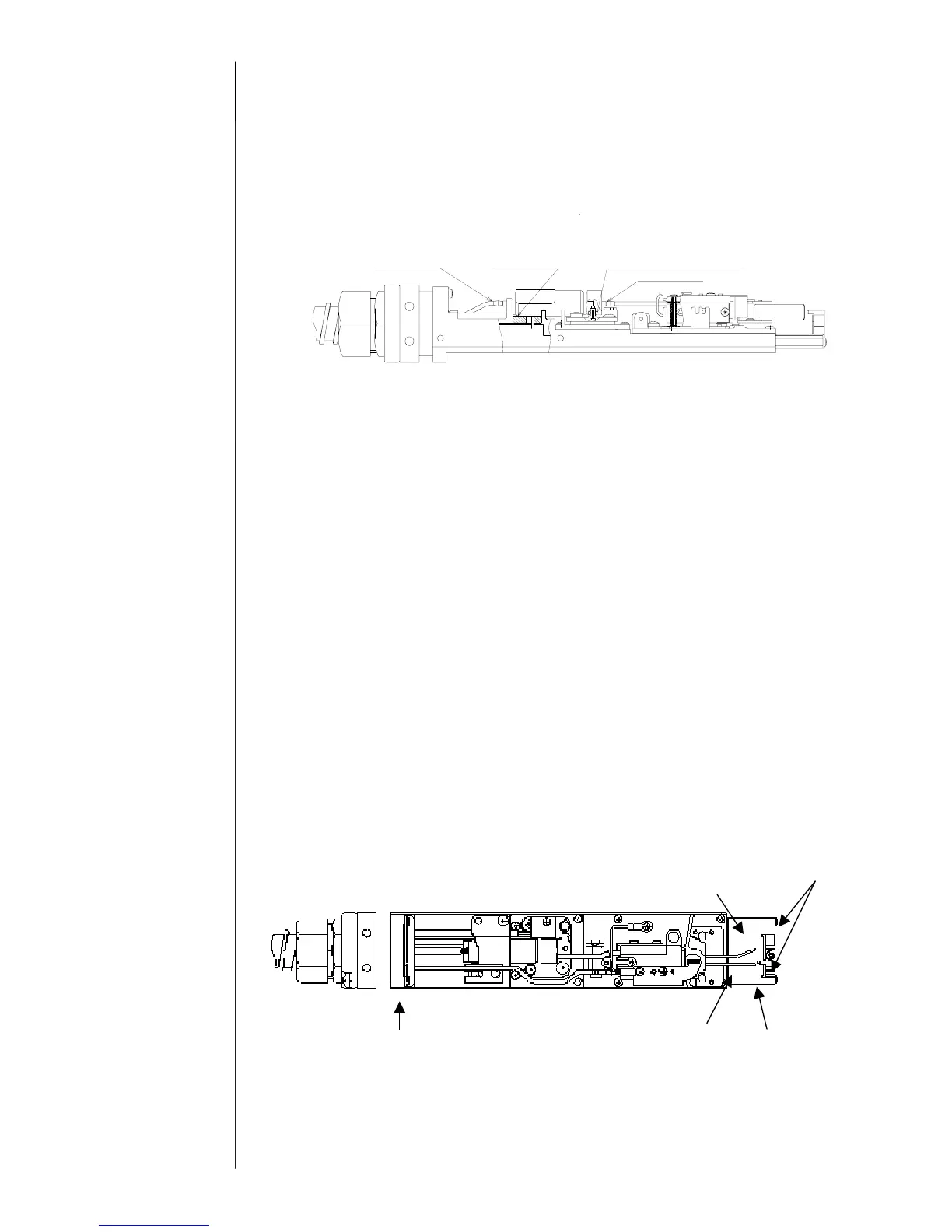
(9) Connect the ink-furnishing tube(E) and fasten it by the heating unit joint presser
foot.
“Caution”
(A) Engage the slit of the heating unit joint presser foot as shown in the
following figure.
(B) After dipping the O-ring in makeup ink, connect the ink-furnishing tube.
(Damage prevention of O-ring)
(10)
Attach the sealing valve.
(11)
Fix the connector and attach the head base rear cover.
(12)
After the completion of the assembly, spurt ink and confirm that there is no leak
from each terminal area.
(13)
Attach all of the covers.
(14)
If “Ink Heating Too High”, “Heating Unit Sensor Fault” or “Ink Heating Current Fault”
occurs, the “Ink temperature correction” is automatically set to “0: disable.”
In that case, select the System environment setup screen from the Maintenance
menu screen, and change the “Ink temperature correction” to “1: enable.”
(15)
Confirm the print state. In the case where the set value of the excitation voltage
is changed at the occurrence of fault, reset the set value.
6.7 Gutter base group Replacement Procedure
When damaging the gutter and the gutter base, the gutter base group must be replaced.
Perform it by the following procedure.
(1)
Unloosed the gutter base setscrews and remove the gutter base group from the
head base.
(A) The O-ring P2.2 is disposed between the gutter base group and the head base.
(2)
Remove the APH shield and attach it to a new gutter base group.
(3)
Put the O-ring P2.2 into the gutter base.
(4)
Attach the gutter base on the head base.
Two gutter base setscrews
APH shield
O-ring P2.2
Head base
Gutter base
 Loading...