4-21
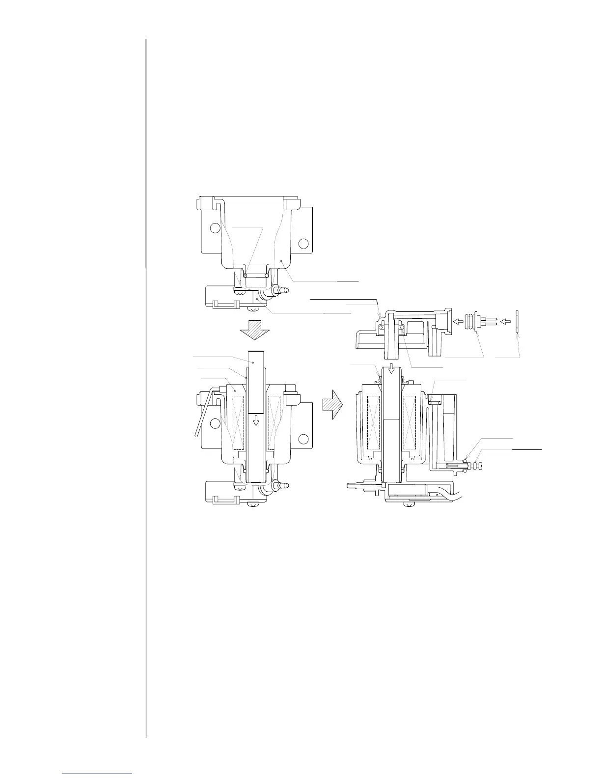
4.9.3 Viscometer assembly procedure
(A) Replace the cylinder, and then insert the plunger. Handle the plunger with tweezers
making sure that no dust adheres to the surface of plunger.
(B) Set the collar to cylinder, taking care with its orientation (with the convex up).
(C) Make sure that an O-ring is set in the viscometer cover, and then assemble the cover
into the viscometer case.
(D) Attach the three viscometer setscrews and tighten them. (Tighten the screws with
reasonable force using screwdriver. Tightening the screws excessively will break the
threads.)
4.9.4 Viscometer attaching procedure
(A) Set the O-ring and squeezing pin on the viscometer OUT side, and use the two
setscrews to attach them to the circulation unit.
(B) Plug in the connectors of lead wires again.
(C) Connect the viscometer IN-side tube (mark G).
Note: After reassembly, it may be necessary to replace the ink and/or calibrate
the viscometer.
When disassembling and washing during installation:
Calibrate the viscometer without replacing the ink.
When replacing the viscometer during installation:
Calibrate the viscometer without replacing the ink.
When replacing the viscometer in cases other than installation:
First replace the ink, then calibrate the viscometer.
O-ring
Viscometer case
Viscometer IN joint
Viscometer cove
 Loading...