4-23
4.10 Print Head Replacement Procedure
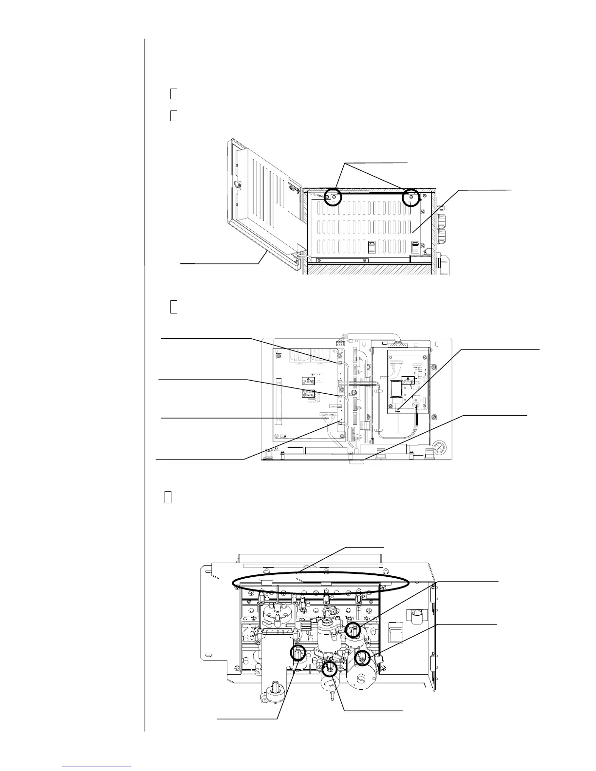
1 Turn off the power supply.
2 Open the operation panel and remove the fixing screws (2 positions).
Remove the board cover.
3 Remove the print head and the connectors (6 positions).
4 Remove the piping connections (4 positions) with the print head.
(Loosen the tube lock and pull out the tube.)
"Caution": Put wiping paper at the end of the tube to provide for an ink drip.
Fixing screw
Operation panel
Board cover
High-voltage wire
APH signal wire
(EZJ94 board: CN2)
Charged signal wire
(EZJ94 board: CN3)
Excitation signal wire
EZJ94 board: CN5
Cover switch, etc.
(EZJ94 board: CN7)
FG wire
(Grounding)
 Loading...