Installing the
HP
3235
18
Refer to Figures
10
and
II
to
install plug-in modules.
I. Verify
the
mainframe
is
in standby
power
(LINE
switch
to
STBY and
fan
is
not operating).
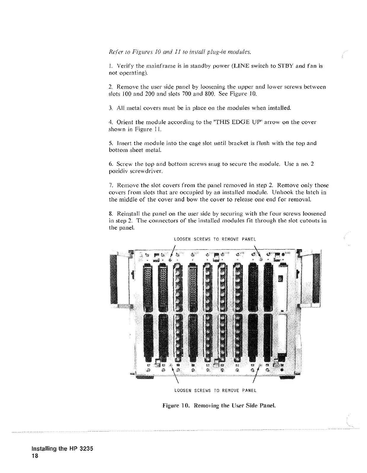
2.
Remove the user side panel
by
loosening
the
upper
and lower screws between
slots
I 00 and 200
and
slots
700
and
800.
See Figure
10.
3.
All metal covers must be in place
on
the
modules when installed.
4.
Orient the module according
to
the "THIS
EDGE
UP" arrow on
the
cover
shown
in
Figure
II.
5.
Insert the
module
into the cage slot until bracket
is
flush with the
top
and
bottom sheet metal.
6.
Screw the top and bottom screws snug to secure the module. Use a no. 2
pozidiv screwdriver.
7.
Remove
the
slot covers
from
the panel removed in step
2.
Remove only those
covers
from
slots
that
are occupied
by
an installed module. Unhook
the
latch in
the middle
of
the cover and bow the cover
to
release
one
end
for
removal.
8.
Reinstall
the
panel on
the
user side
by
securing with the
four
screws loosened
in step
2.
The
connectors
of
the installed modules
fit
through the slot
cutouts
in
the panel.
LOOSEN
SCREWS
TO
REMOVE
PANEL
LOOSEN
SCREWS
TO
REMOVE
PANEL
Figure 1 0. Removing the User Side Panel.
Artisan Technology Group - Quality Instrumentation ... Guaranteed | (888) 88-SOURCE | www.artisantg.com
 Loading...