Installing a Bus
Access
(or Extender Module)
This section applies
to
a
mainframe
system only
(no
extenders
to
install)
although
the installation
procedure
for an Extender Module
is
the
same as
that
for
a Bus
Access Module.
If
you have extenders in your system, you begin
extender
module installation by the procedure given in the previous section titled
!!Installing Extendersn.
Each mainframe comes with a module
for
extending
the
analog bus. Shipped in-
dividually
is
either:
I. Bus Access
Module
(P/N 03235-66204) shipped with a
standard
mainframe. This
module
allows "hard-wired"
external
connections
to
the
analog bus in a
mainframe
only
system.
2.
Extender
Module
(P /N HP 34560A) shipped
with
an
option
560
mainframe and each extender frame. This module extends
both
the analog
and digital buses.
The
digital bus links the
control
of
the
mainframe
to
each
extender. This module has relay contacts
that
can
be
programmed
to
open
and
close
the
external
connections
to
the
analog buses.
NOTE
The
Bus
Access
Module
provides
only
a "hard-wired" connection
to
analog
buses
while the
Extender
Module
provides relay contacts that can be
programmed
to
open or close
cmmccthms
to the analog huses.
WARNING
The
11
P 3235 main/: anzc and c.x:lcndcr lrmnc
and
ccf'fain plug-in rnodules· alloH
1
up
to
350V
peal<
ro
he
O{JfJiicd
to
!he analog huscs. Vo!ragc.\
present
on !he huses
are a!:w present on rhe
rerminct!.~
and
screws
u/
!he analuK e
..
:
..
:tender
connec/ur.-,·.
These
mnnectors
an
/neared on the 03235-li6204 Hus A cccss
Module
and
musr he
accessed
by
quali/inl,
.\l!rvice-/roined
personnel only.
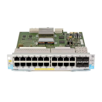
Figure
17
shows
both
of
these modules.
The
modules
are
shipped uninstalled so
that analog bus extender cables can be added prior
to
module installation in a
frame. If no analog bus extending
is
to
be done, simply install
the
module in the
frame for possible
future
use.
After
cables are installed, install
the
modules
in
the frames as follows.
a.
Remove
the
metal silkscreened panel which
covers
the CROSSGUARD
through
POWER
SUPPLY
system modules.
Six
no. 2 pozidriv screws hold
this panel in
place and are shown in Figure
18.
b.
If
you are making analog bus connections
to
the
Bus Access Module,
refer
to
the section titled "Installing Analog Extender Cables"
under
Installing
Extenders.
Installing the
HP
3235
27
Artisan Technology Group - Quality Instrumentation ... Guaranteed | (888) 88-SOURCE | www.artisantg.com
 Loading...