Moving the System to the Installation Site
The customer should determine the path that must be taken to move the system from the delivery location
to the installation site. The customer should verify that the height of all doorways, elevators, and so on are
sufficient to allow moving the system to the installation site. The customer should also verify that the
weight limitations of elevators, ramps, and so on are sufficient to allow moving the system to the
installation site. If the height or weight of the system can cause a problem when the system is moved to
the installation site, the customer should contact their local site planning, marketing, or sales
representative.
Power and Electrical Requirements
Redundant power and line cords are standard on the Eserver pSeries 690. The system uses dual A/C
power cords. For maximum availability, each of the line cords should be fed from independent power grids.
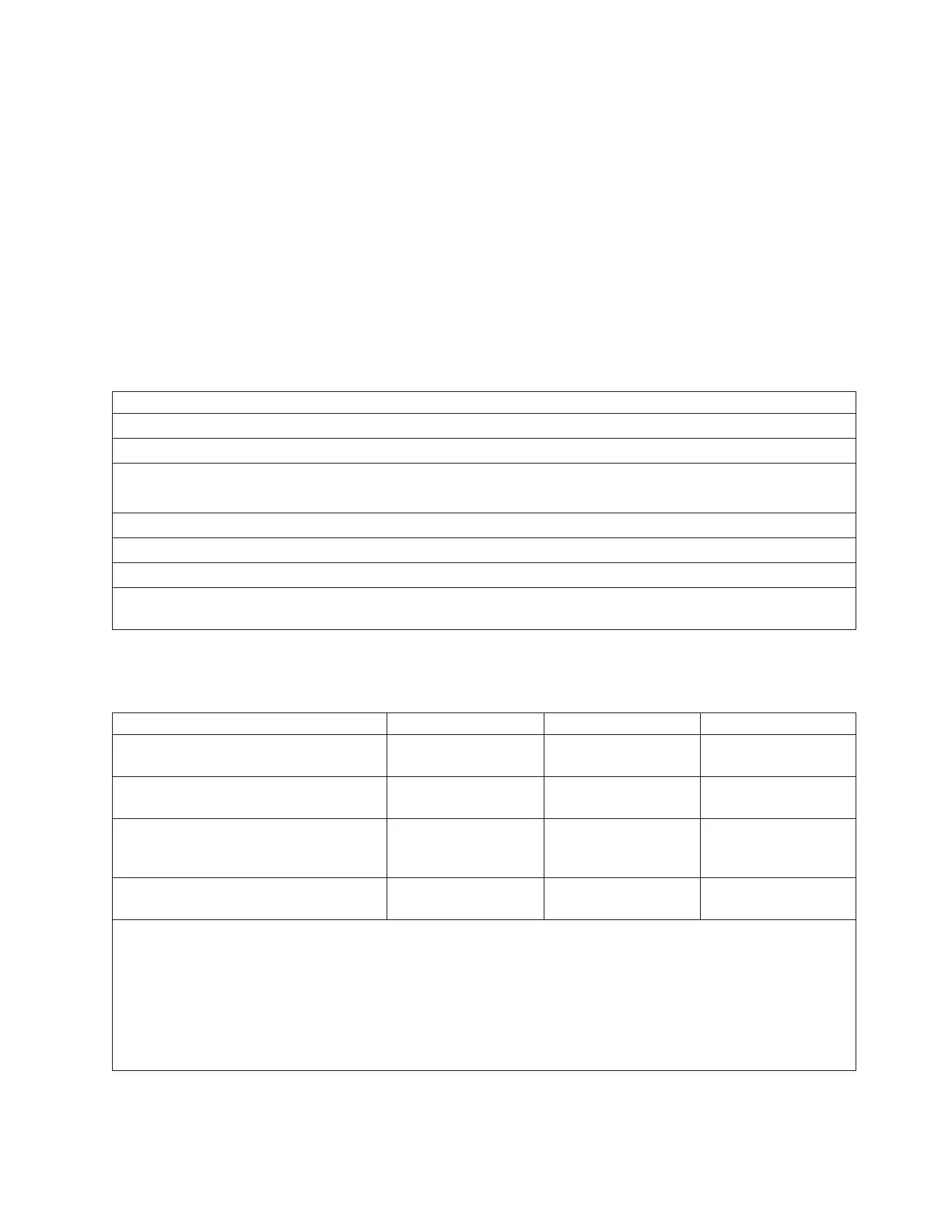
The following table illustrates electrical and thermal characteristics for the Eserver pSeries 690.
Electrical/Thermal Characteristic
Rated Voltage (V ac, 3 phase) 200 to 240 380 to 415 480
Rated Current (A, per phase) 45 25 20
Frequency (Hertz) 50 to 60 50 to 60 50 to 60
Power (Maximum in kW) 15.7 15.7 15.7
Typical, full load power factor (pf) 0.99 0.97 0.93
Inrush current (Amps) 162 max (see note below)
Thermal output (Maximum kBtu/hr) 53.3 53.3 53.3
Note: Inrush currents occur only at initial application of power (very short duration for charging capacitors). No
inrush currents occur during the normal power off-on cycle.
The following table illustrates the line cord options for the Eserver pSeries 690 with their geographic,
breaker rating, and cord information.
3-Phase Supply Voltage (50/60 Hz) 200-240 V 380-415 V 480 V
Geography United States, Canada,
Japan
Europe, Middle East,
Africa, Asia Pacific
United States, Canada
Customer Circuit Breaker Rating (see
Note 1 below)
60 A 30 A 30 A
Cord Information 6 and 14 foot, 6 AWG
line cord
14 foot, 6 or 8 AWG
line cord, (electrician
installed)
6 and 14 foot, 10 AWG
line cord
Recommended Receptacle IEC309, 60 A, type
460R9W (not provided)
Not specified,
electrician installed
IEC309, 30 A, type
430R7W (not provided)
Notes:
1. The exact circuit breaker ratings may not be available in all countries. Where the specified circuit breaker ratings
are not acceptable, use the nearest available rating. Use of a time delayed circuit breaker is recommended.
2. In two-frame systems, frame B receives its power from frame A. The power to frame B is 350 V DC fed from the
BPD through UPIC cables.
3. IBM strongly recommends the use of a metal backbox with line cords using IEC-309 plugs. For additional
information about this recommendation, see Chapter 11, “Power Cords and Electrical Needs,” on page 337.
Chapter 2. Physical Characteristics of Systems 163
 Loading...


