S00 Rack Weight Distribution and Floor Loading
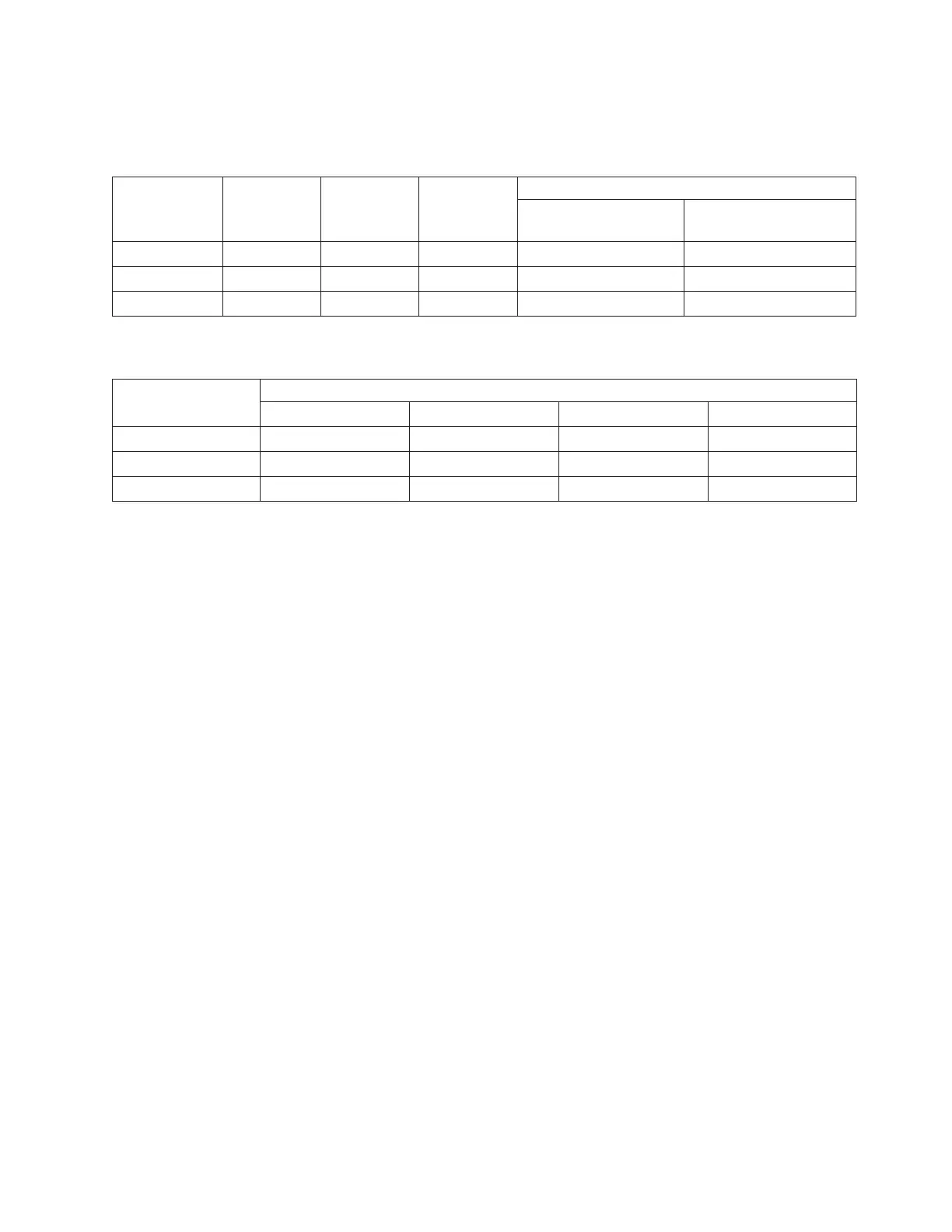
The S00 rack can be extremely heavy when several drawers are present. The following table shows the
necessary weight distribution distances for the S00 rack when it is loaded.
Rack System
Weight (1)
lbs(kg)
Width (2)
in(mm)
Depth (2)
in(mm)
Weight Distribution Distance (3)
Front & Back
in(mm)
Left & Right
in(mm)
7014-S00 (4) 1309 (594) 25.5 (650) 35 (889) 22 (559), 19.2 (487.7) 18 (457.2)
7014-S00 (5) 1309 (594) 25.5 (650) 35 (889) 22 (559), 19.2 (487.7) 0.0 (0.0)
7014-S00 (6) 1309 (594) 25.5 (650) 35 (889) 22 (559), 19.2 (487.7) 13 (330.2)
The following table shows the necessary floor loading for the S00 rack when it is loaded.
Rack Floor Loading
Raised kg/m2 Non-Raised kg/m2 Raised lb/ft2 Non-Raised lb/ft2
7014-S00 (4) 304 260.2 62.3 53.3
7014-S00 (5) 561.5 517.5 115 106
7014-S00 (6) 840 296 70 61
The following notes are for both the weight distribution distance table and the floor loading table.
Notes:
1. Maximum weight of fully populated rack, units are lbs with kg in parentheses.
2. Dimensions without covers, units are inches with mm in parentheses.
3. The weight distribution distance in all four directions is the area around the rack perimeter (minus
covers) necessary to distribute the weight beyond the perimeter of the rack. Weight distribution areas
cannot overlap with adjacent computer equipment weight distribution areas. Units are inches with mm
in parentheses.
4. Weight distribution distance is 1/2 the service clearance values shown in the figure plus cover
thickness.
5. No left and right weight distribution distance.
6. Left and right weight distribution distance required for a 70 lb/ft2 raised floor loading objective.
Chapter 2. Physical Characteristics of Systems 29
 Loading...


