Guide for Raised-Floor Preparation
A raised floor is not required for the Eserver pSeries 690 (except in Canada). However, it is
recommended for optimum system cooling and cable management. Raised floor cutouts should be
protected by electrically nonconductive molding, appropriately sized, with edges treated to prevent cable
damage and to prevent casters from rolling into the floor cutouts.
Front-service access is necessary on the Eserver pSeries 690 to accommodate a lift tool for the
servicing of large drawers (the managed server, IO drawer, and media subsystems). Front and rear service
access is necessary to accommodate the lift tool for servicing of the optional integrated battery feature
(IBF).
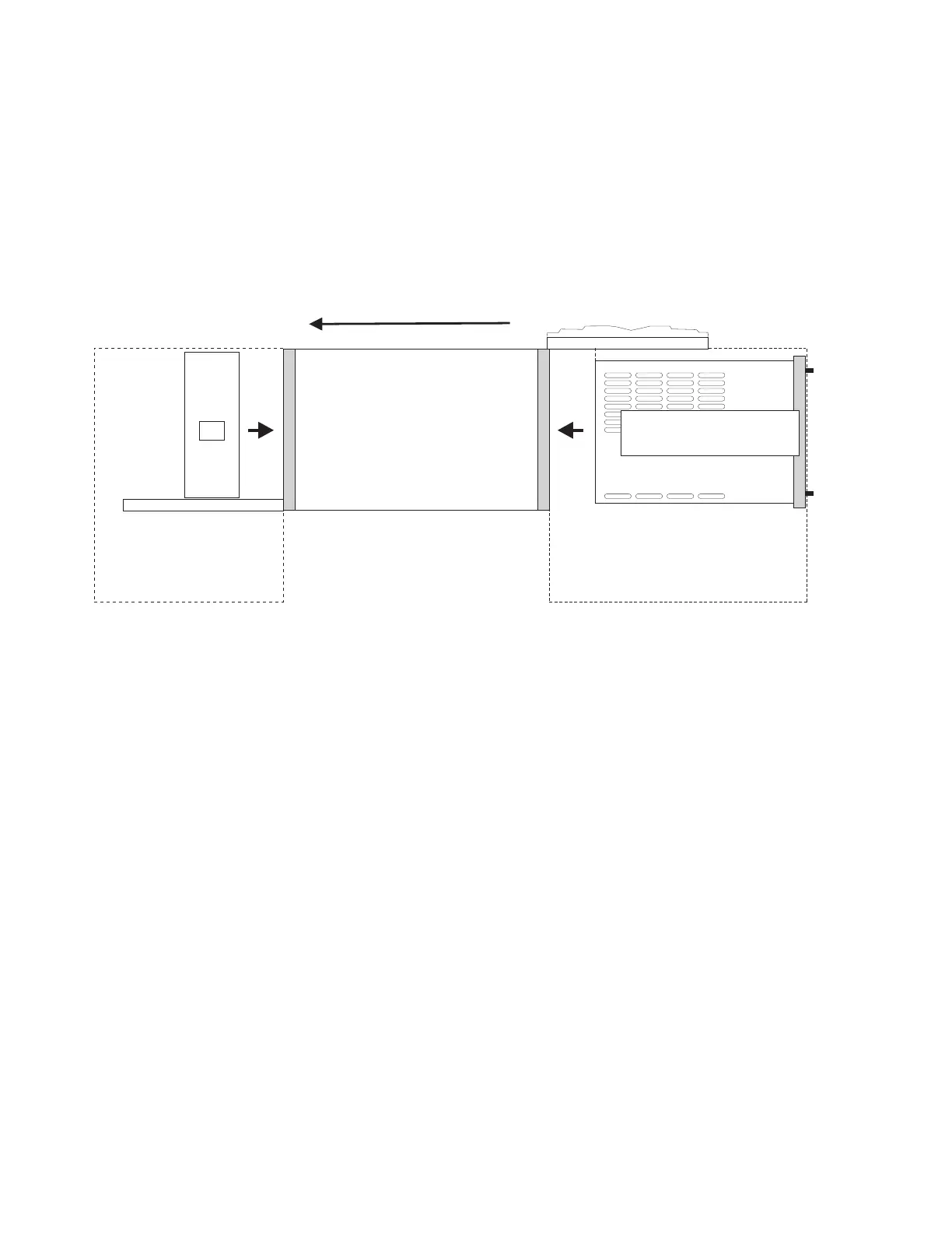
Airflow Direction
Top View
Drawer Subsystems:
Managed Server: ~39” deep
I/O: ~34” deep
!
!
Floor Plan Considerations for Single Units
Lift Tool Service
Clearance
Lift Tool Service
Clearance
IBF
Cutting and Placement of Floor Panels
This section provides recommendations for making the necessary openings in the raised floor for installing
the Eserver pSeries 690.
Note: The following illustration is intended only to show relative positions and accurate dimensions of floor
cutouts. The illustration is not intended to be a machine template and is not drawn to scale.
The x-y alphanumeric grid positions are used to identify relative positions of cutout floor panels that may
be cut in advance.
1. Determine whether the system you will be installing has one or two frames.
2. Measure the panel size of the raised floor.
3. Verify the floor panel size. The floor panel size illustrated is 600 mm (23.6 in.) and 610 mm (24 in.)
panels.
4. Ensure adequate floor space is available to place the frames over the floor panels exactly as shown in
the illustration. Refer to “Considerations for Multiple System Installations” on page 192 for front-to-back
and side-to-side clearances. Use the plan view if necessary. Consider all obstructions above and below
the floor.
5. Identify the panels needed, and list the total quantity of each panel required for the installation.
6. Cut the required quantity of panels. When cutting the panels, you must adjust the size of the cut for
the thickness of the edge molding you are using. The dimensions shown in the illustrations are finished
dimensions. For ease of installation, number each panel as it is cut, as shown in the following
illustrations.
182 Site and Hardware Planning Information
 Loading...


