l Chapter 7 Selection and Dimensions
- 103 -
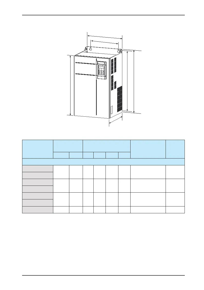
Figure 7-2 Physical appearance and mounting dimensions of the CS200 (sheet metal housing)
Table 7-2 Mounting dimensions of the CS200
AC Drive Model
Mounting Hole
(mm)
Overall Dimensions
(mm)
Mounting Hole Diameter
(mm)
Weight
(kg)
A B H H1 W D
Three-phase 380 to 480 V
CS200-4T18.5GB
195 335 350 / 210 192 Ø6 9.1
CS200-4T22GB
CS200-4T30GB
230 380 400
/ 250 220
Ø7 17
CS200-4T37GB
CS200-4T45GB
245 523 523 540 300 275 Ø10 35
CS200-4T55GB
CS200-4T75GB 270 560 550 576 338 315 Ø10 51.5
Notes:
The data and models recommended in the table are for reference only. The diameter of the cable the user selects
must not exceed the terminal dimensions in the gure.
The prerequisite of cable selection is the recommended value of PVC insulated copper wire or cable diameter at
the ambient temperature of 40°C in the steady state. For details, see the section 12.4 in the IEC 60204-1-2005.
 Loading...


