Chapter 4 Operations
- 46 -
In the preceding gure, DI3 and DI4 are selected for input of multi-speed signals. Set the empty bit to 0. Based on
state combination of the two binary values, multi-speed is selected.
When (DI3, DI4) = (0, 1), the binary values (0, 1) are combined into value 2, indicating that the speed set in b5.02/
b5.06 is use
d
.
When b7.01 = 0, the value of b5.02 is used as the frequency reference no matter whether the CS200 runs in the
upward or downward direction.
When b7.01 = 1, the value of b5.02 is used as the frequency reference if the CS200 runs in the upward direction.
The value of b5.06 is used as the frequency reference if the CS200 runs in the downward direction.
The CS200 supports a maximum of two DI terminals used for input of multi-speed signals. You can also use less
than one DI terminal for input of the multi-speed signal. The state value of the empty bit is considered as 0.
4.6 Use of DI Terminals
The CS200 provdes ve DI terminals (DI1 to DI5). Extra ve DI terminals (DI6 to DI10) are provided by the I/O
extension card.
The internal hardware of the DI terminals has the 24 VDC power supply for detection. The DI signal can be input to
the AC drive after you short the DI terminal and the COM port.
The AC drive also provides the DI lter time (b3.21) to the DI signal tom improve the anti-interference level.
The preceding ten DI terminals can be defined in function parameters b3.01 to b3.10. For details, see the
descriptions of b3.01 and b3.10.
4.7 Use of DO Terminals
The CS200 provides three DO terminals (FM, DO1 and T/A-T/B-T/C), amongst which FM and DO1 are transistor
output and can drive 24 VDC low-voltage circuit, and TA/TB/TC is relay output and can drive 250 VAC control
circuit.
Extral digital outputs (DO2 and P/A-P/B-PC) are provided by the I/O extension card. The DO2 is transistor output
and the P/A-P/B-P/C is relay output.
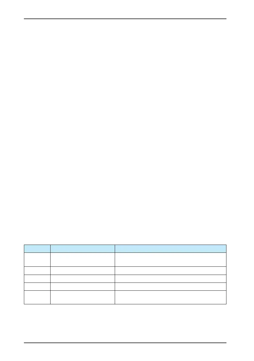
The functions of the DO terminals can be defined in b3.14 to b3.18. For details, see the descriptions of the
parameters in group b3.
Terminal Corresponding Function Code Output Feature Description
FM-CME
When the thousand's digit of b3.18 =
1, the digital output is used
Transistor output, drive capacity: 24 VDC, 50 mA
T/A-T/B-T/C b3.14 Relay output, drive capacity: 250 VAC, 3 A
P/A-P/B-P/C b3.15 Relay output on the extension card, drive capacity: 250 VAC, 3 A
DO1-CME b3.16 Transistor output, drive capacity: 24 VDC, 50 mA
DO2-CME b3.17
Transistor output on the extension card, drive capacity: 24 VDC,
50 mA
 Loading...


