Chapter 3 Mechanical and Electrical Installation
- 30 -
3.2.2 Main Circuit Wiring
The CS200 of 75 kW and below has the built-inn braking unit and you need to connect braking resistor to the main
circuit only. The CS200 of 90 kW and above must connect the external braking unit.
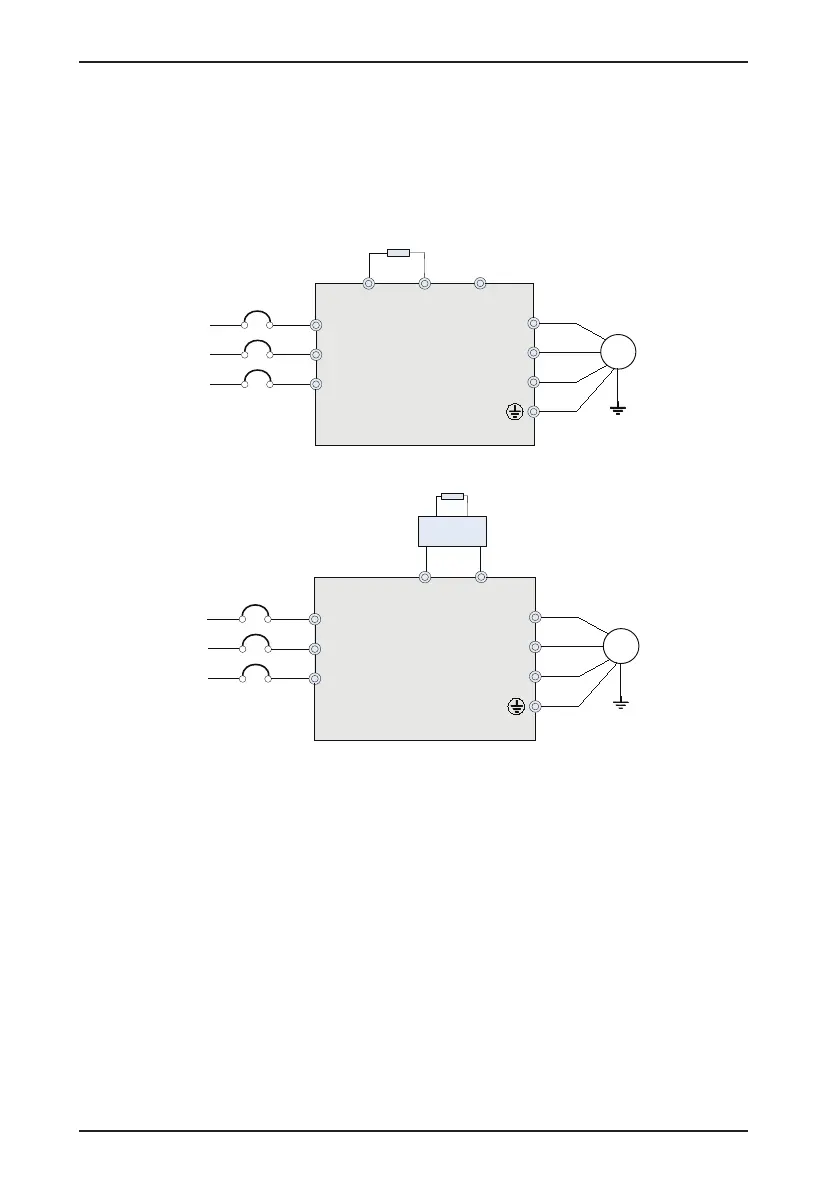
Figure 3-13 Main Circuit Wiring
W
V
U
(-)
CS200
MCCB
T
S
R
T
S
R
BR (+)
M
Braking resistor
Three-phase 380/
480 V, 50/60 Hz
Main circuit wiring of the CS200 (three-phase 380 to 480 V, 18.5 to 75 kW)
W
V
U
(-)
CS200
MCCB
Three-phase 380/
480 V, 50/60 Hz
T
S
R
T
S
R
(+)
M
Braking resistor
Braking unit
Main circuit wiring of the CS200 (three-phase 380 to 480 V, 90 kW and above)
3.2.3 Precautions on Main Circuit Wiring
1. Power input terminals R, S, T
•
The cable connection on the input side of the AC drive has no phase sequence requirement.
•
The specification and installation method of external power cables must comply with the local safety
regulations and related IEC standards.
•
Use copper conductors of a proper size as power cables according to the recommended values in section
8.3.
2. DC bus terminals (+), (-)
•
Terminals (+) and (-) of DC bus have residual voltage after the AC drive is switched off. After indicator
CHARGE does off, wait at least ten minutes before touching the equipment. Failure to comply may result
in electric shock.
•
When connecting external braking components for the AC drive of 90 kW and above, never reverse (+)
and (-). Failure to comply may result in damage to the AC drive and even cause a re.
 Loading...


