Chapter 2 Product Information
- 19 -
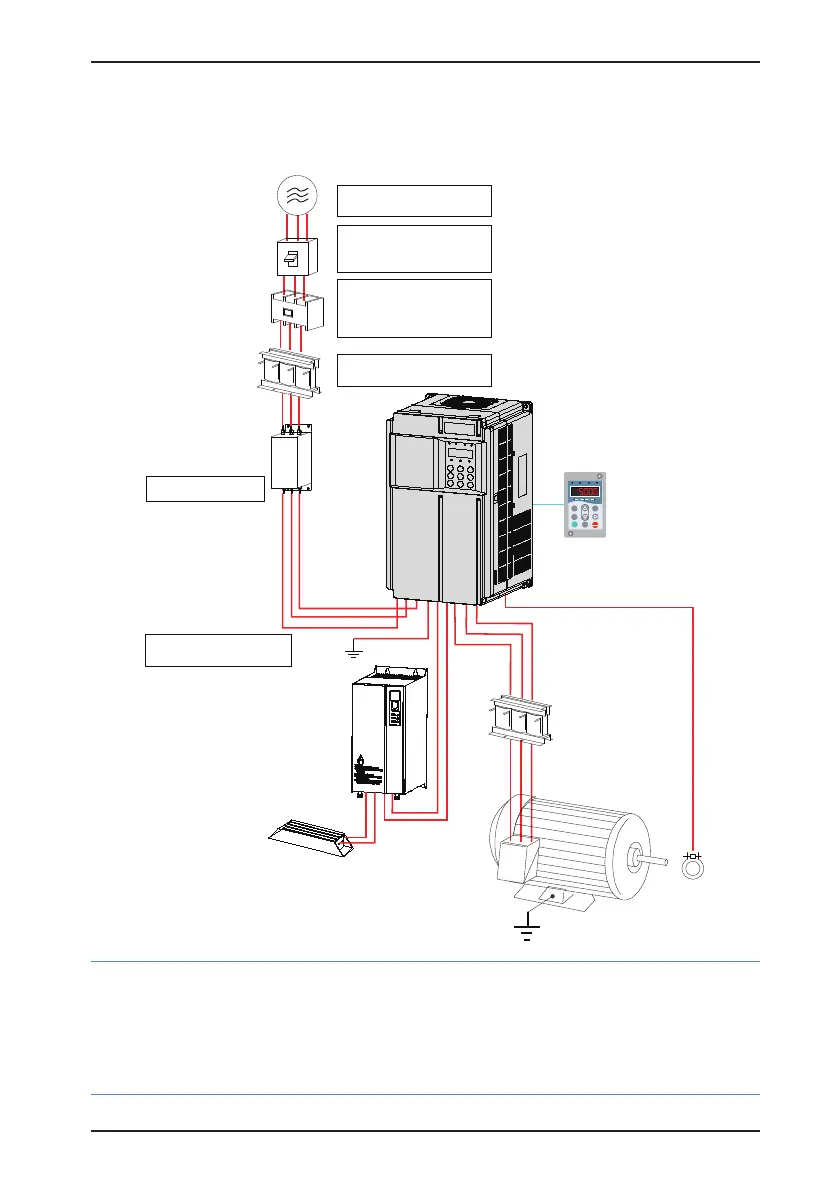
2.4 Connection to Peripheral Devices
Figure 2-4 System conguration of the CS200
Ground
AC input
reactor
Electromagnet
ic contactor
Molded case circuit
breaker (MCCB) or
earth leakage circuit
breaker (ELCB)
Three-phase AC
power supply
Use within the allowable power supply
specification of the servo drive.
Select a proper circuit breaker to resist
large in-rush current that flows into the
AC drive at power-on.
Reliably ground the motor and the
servo drive to prevent electric shock.
Suppress the high order harmonic to
improve the power factor.
Braking resistor
EMC filter on
the input side
To guarantee safety, use an
electromagnetic contactor. Do not use
it to start or stop the AC drive because
such operation reduces the service life
of the servo drive.
Reduce the electromagnetic
interference on the input side.
Output
reactor
P(+)
MF.K
RUN
STOP
RES
QUICK
PRG ENTER
RUN
LOCAL/REMOT FED/ REV TUNE/ TC
RPM
%
A VHz
BR
Braking unit
(+)
(-)
Motor
Ground
Traveling
cable
Braking
mechanism
R
S
T
W
V
U
CS200
Note
•
Never install the capacitor or surge suppressor on the output side of the AC drive. Otherwise, it may
cause faults to the AC drive or damage to the capacitor and surge suppressor.
•
Inputs/Outputs (main circuit) of the AC drive contain harmonics, which may interfere with the
communication device connected to the AC drive. Therefore, install an anti-interference lter to
minimize the interference.
 Loading...


