Chapter 3 Mechanical and Electrical Installation
- 38 -
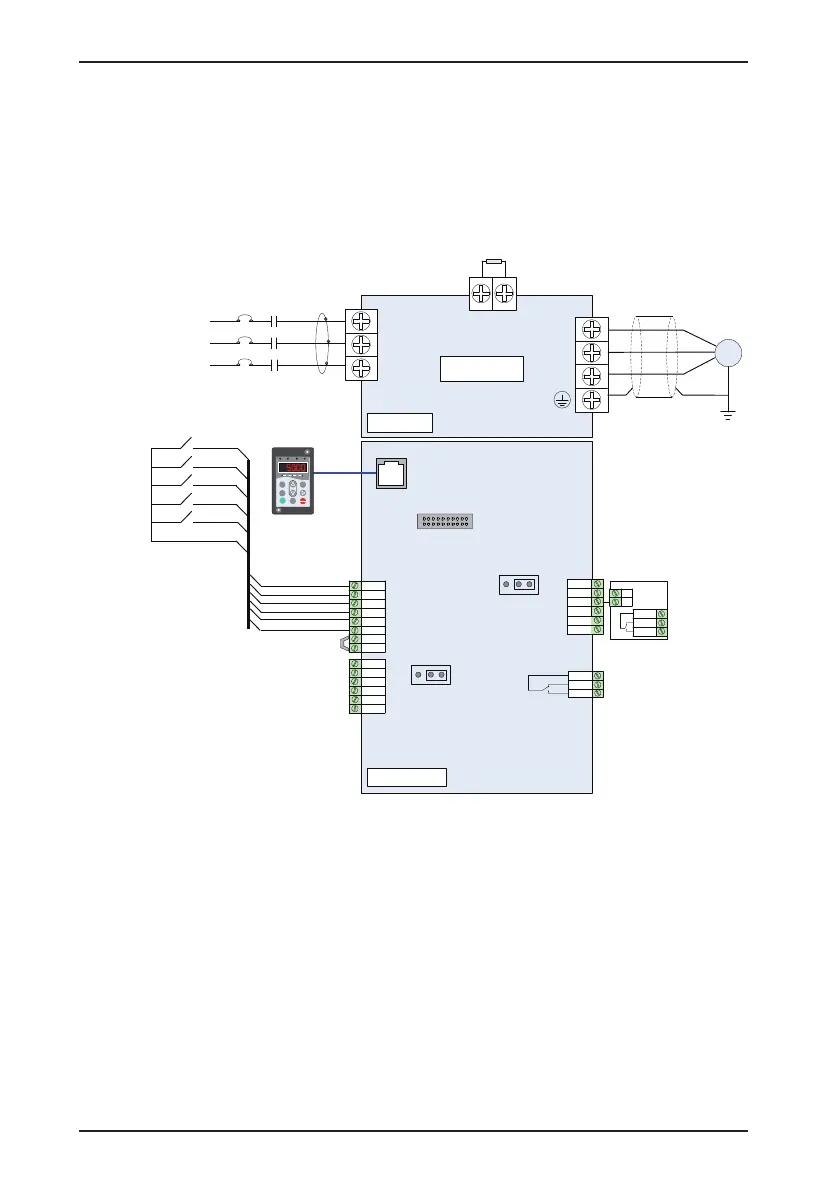
3.2.6 Typical Wiring Example of the CS200
Here takes the CS200 of 37 kW as an example to describe the commonly used wiring method of the drive when
it is applied in the construction elevator, that is, terminal control, multi-speed reference, brake output control, fault
reset and fault output.
Figure 3-22 Typical wiring exapmple of the CS200
250 VAC 10 mA to 3 A
30 VDC 10 mA to 1 A
Interface of external
operation panel
Interface of
extension card
CS200
R
S
T
M
+
BR
U
V
W
J11
10V
AI1
AI2
PE
COM
GND
AO1
DO1
GND
COM
OP
24V
T/A
T/B
T/C
Brake output (NC/NO)
Three-phase AC
power supply
L2
L3
L1
MCCB
MC
magnetic ring
Braking resistor
Shielded cable
Main circuit
Control circuit
Jumper
DI1
DI2
DI3
DI4
Forward run
Reverse run
Multi-speed 1
Multi-speed 2
Fault reset
CME
DI5
J9
I V
AI2 voltage/
current selection
J7
I V
AO1 voltage/
current selection
FM
COM
J13
MF.K
RUN
STOP
RES
QUICK
PRG ENTER
RUN
LOCAL/REMOT FED/ REV TUNE /TC
RPM
%
A VHz
Relay card
MD28IR1
DO
24V
R/A
R/B
R/C
Fault output
(Wind a turn)
Circular
 Loading...


