Chapter 3 Mechanical and Electrical Installation
- 35 -
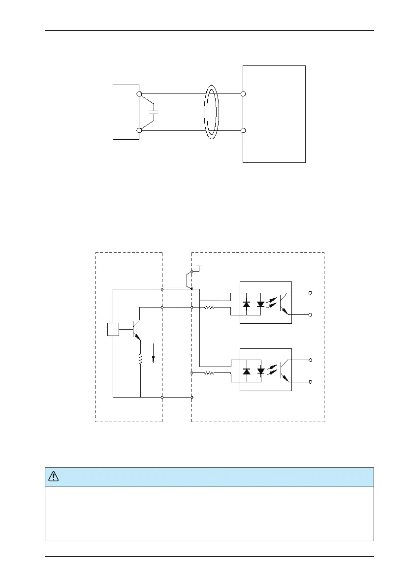
Figure 3-17 Install lter capacitor or ferrite magnetic core
AI1
GND
Cross or wind two or three
turns in the same direction.
0.022 uF
50 V
Ferrite magnetic core
C
CS200
■
DI Wiring
Where possible, use shielded cables shorter than 20 m long to carry digital signals. If the active driving is used,
take necessary ltering measure to prevent the digital signals causing interference on the power supply. In these
circumstances, you are recommended to use the contact control mode.
1. SINK wiring
Figure 3-18 SINK wiring mode
0V
DI5
DI1
OP
+24V
+24V
2.
4k
2.4k
3.3Ω
NPN
Signal
External controller AC drive control board
+VCC
COM
It is the most commonly used wiring mode. To apply an external power supply, remove the jumper between the
+24V and the OP terminals. Connect the positive sige of the external power 24V to the OP terminal, and the
external power 0V to the corresponding DI terminal via the contact on the external controller.
In the SINK wiring mode, do not connect the DI terminals of different AC drives in parallel, otherwise, a digital input fault
will occur. If it is required to connect different AC drives in parallel, connect a diode in series a the digital input. The diode
must satisfy:
•
Forward current rating IF > 10 mA
•
Forward voltage drop UF < 1 V
 Loading...


