Chapter 5 Function Code Table
- 65 -
Function
Code
Parameter Name Function Description Setting Range Default
b6.08
Brake feedback
purpose
It involves the use of faults 41# and 42#. For
details, see the description of these two faults.
0: Braking feedback not used
There is no braking feedback contact input to the
AC drive or the braking feedback function is not
required.
1: Used for direction at brake action
Only one brake feedback contact is required
and is connected to the input function 11 for this
application. The brake feedback signal is monitored
in the whole process. When the actual feedback
action is reversed to the brake output logic (output
function 1), the fault is reported.
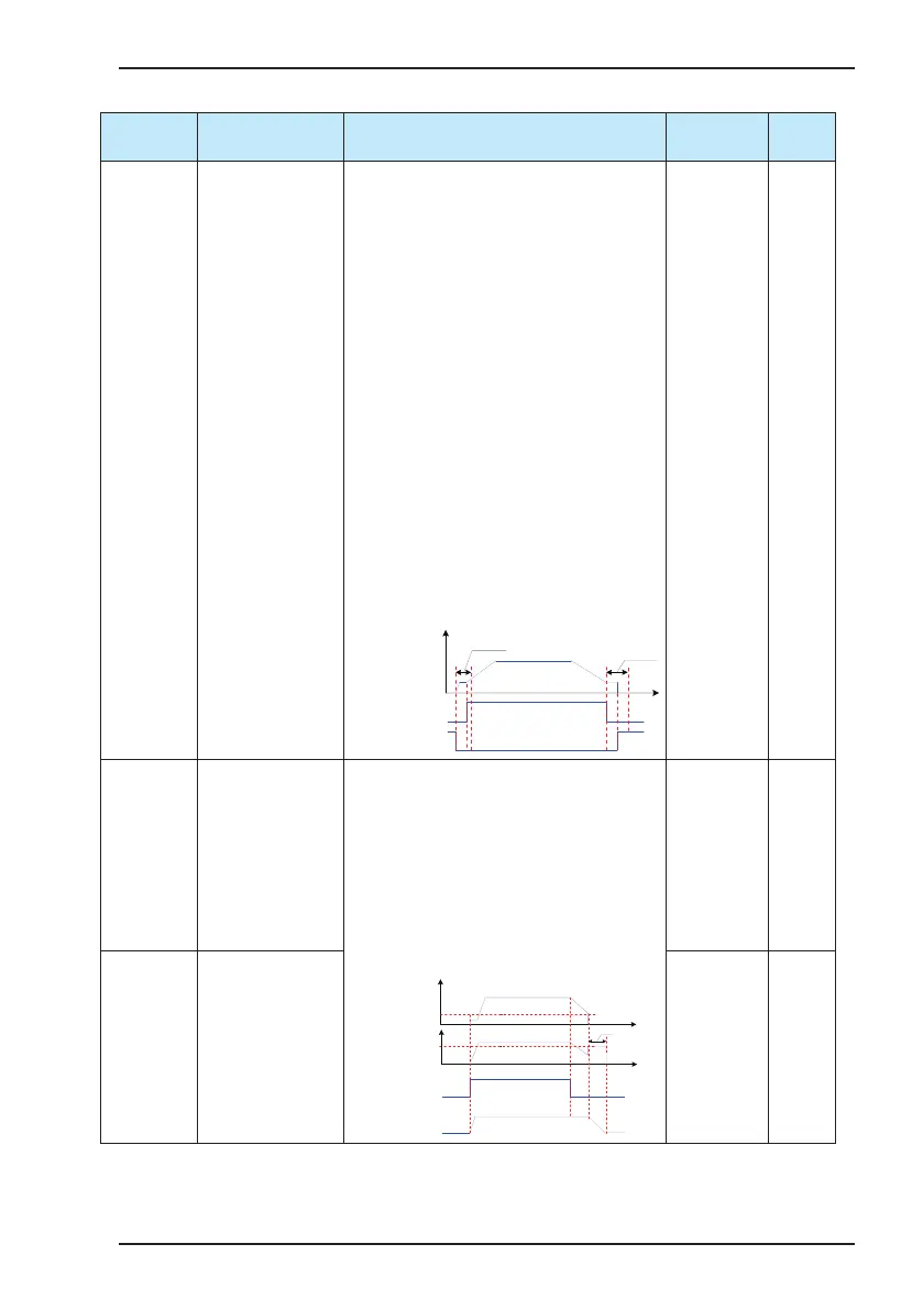
2: Used for whole process monitoring
The brake release time and brake apply time are
determined by the brake feedback contact signal.
Once the AC drive is powered on, the brake
feedback signal is detected. In such application,
one brake release contact and one brake apply
contact need be connected to the AC drive. The
correct application logic diagram is shown as below:
Frequency
reference
Input function 11 of brake
release feedback signal
Brake apply
time (b6.06)
Brake release
time (b6.04)
Input function 12 of brake
apply feedback signal
0 to 2 0
b6.10 DC braking current The DC braking current indicates the percentage of
the AC output current to the rated motor current at
DC braking. The larger the value is, the better DC
braking result will be obtained but the motor and
the AC drive will get hotter.
In the process of decelerating to stop, when
the frequency reference falls to the value of this
parameter, the AC drive starts DC braking. After
entering the DC braking state, the AC drive outputs
the brake apply command.
Output frequency
Output current
effective value
Time
Time
RUN command
DC braking frequency
DC braking current
Brake state
Brake apply
time (b6.06)
0% to 120% 0%
b6.11 DC braking frequency Min. frequency
(b1.03) to
50.00 Hz
0.00 Hz
 Loading...


