Chapter 4 Operations
- 48 -
4.10 Brake Time Sequence of the Crane System
The CS200 has the built-in brake time sequence control function. This function requires that an output terminal is
set for the function 1 (brake control). The following gure shows the brake control time sequence.
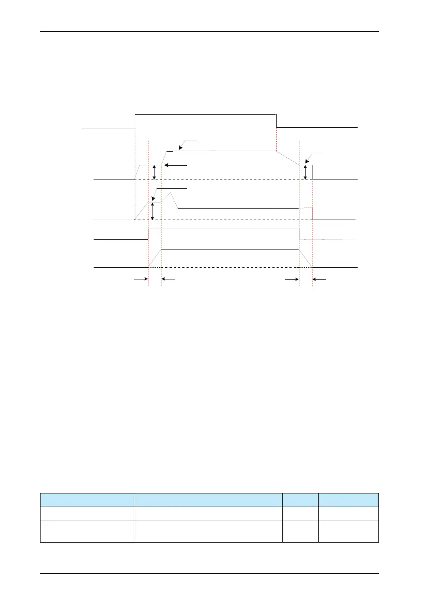
Figure 4-8 Brake control time sequence of the crane system
Brake release time (b6.04)
Brake release
frequency (b6.02)
Brake release
current (b6.03)
Brake apply
time (b6.06)
Brake apply
frequency (b6.05)
RUN
command
Output frequency
Output current
Brake action
Target running frequency
DO brake
release control
Braking mechanism released
Braking state
Braking state
The braking mechanism keeps applied when de-energized and is released when energized. Because the brake
needs to act mechanically, there is a mechanical delay between the brake output signal of the AC drive and the
braking state. The brake release time (b6.04) and the brake apply time (b6.06) must be set according to the actual
mechanical delay of the brake. Theoretically, these two parameters must be a little longer than the mechanical
delay to prevent hook gliding.
Note: The CS200 can implement separate control of upward and downward brake time sequence in the application
of construction elevator. For details, refer to the descriptions of b7.01 to b7.06.
4.11 Setting and Auto-tuning of Motor Parameters
4.11.1 Motor Parameters to Be Set
When the AC drive runs in the vector control mode, accurate motor parameters are required to ensure desired drive
performance and running efciency. This is extremely different from the V/F control (b1.00 = 2).
4.11.2 Motor Auto-tuning
The motor parameters can be obtained through dynamic auto-tuning or static auto-tuning. You can also input the
motor parameters manually.
Auto-tuning Mode Application Result Parameter Setting
Static auto-tuning (complete) It is applied to all applications. Good b0.04 = 3
No-load dynamic auto-tuning
(complete)
It is applied to applications where the motor can be
easily disconnected from the load.
Good b0.04 = 2
 Loading...


