Chapter 3 Mechanical and Electrical Installation
- 29 -
3.2 Electrical Installation
3.2.1 Description of Main Circuit Terminals
The main circuit terminals of the CS200 are arranged as follows:
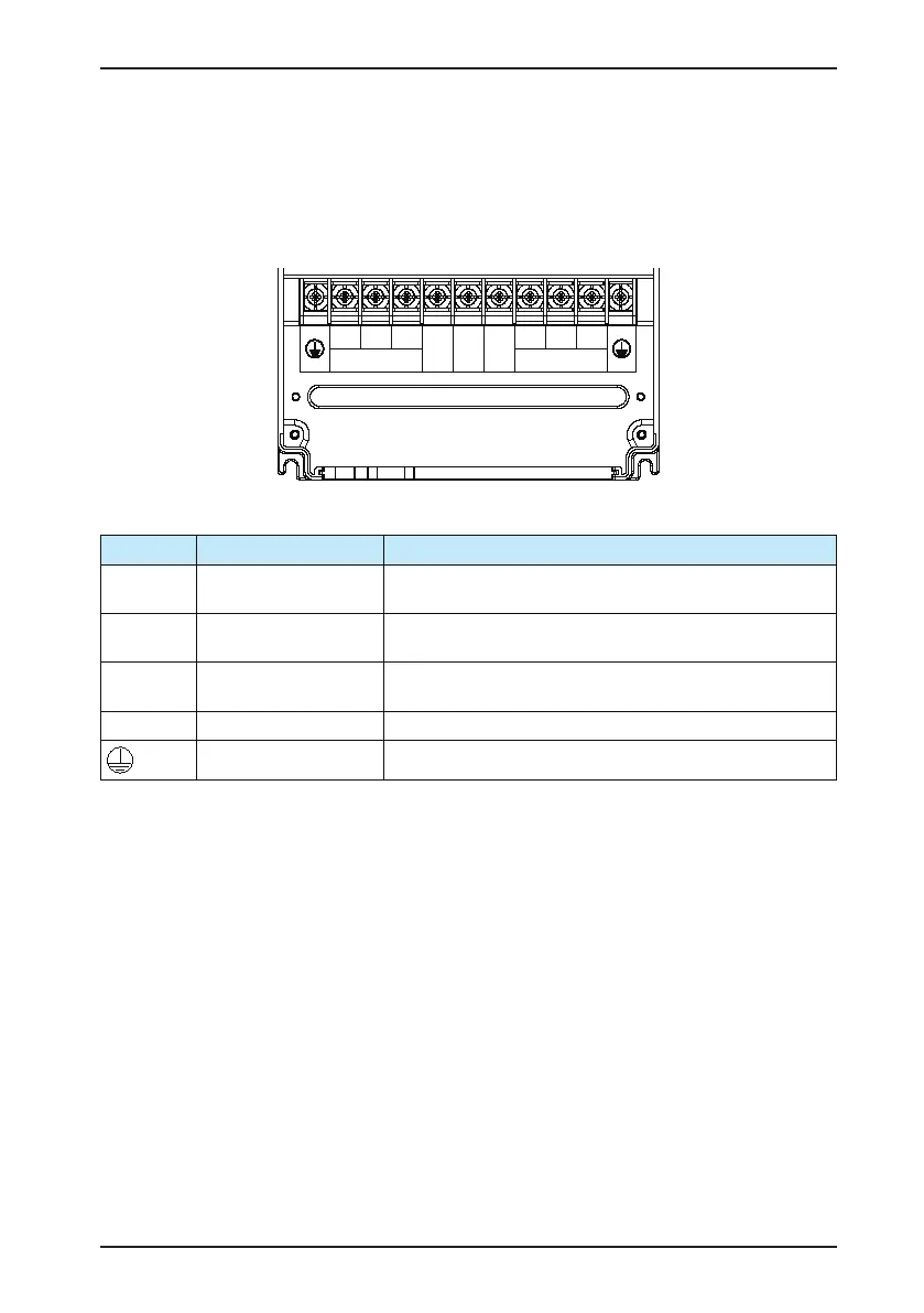
Figure 3-12 Terminal arrangement of the main circuit
MOTOR POWER
R S T
BR (+) (-)
U V W
Table 3-2 Description of main circuit terminals of the CS200
Terminal Name Function Description
R, S, T
Three-phase power input
terminals
Connect to the three-phase power supply.
(+), (-)
Positive and negative
terminals fo DC bus
Common DC bus input point
Connect to the external braking unit for the models of 90 kW and above.
(+), BR
Terminals for connecting
braking resistor
Connect to a braking resistor for the models of 75 kW and below.
U, V, W AC drive output terminals Connect to a three-phase motor.
Grounding terminal Must be grounded.
 Loading...


