Chapter 3 Mechanical and Electrical Installation
- 33 -
3.2.4 Control Circuit Wiring
The control circuit terminals are arranged as follows:
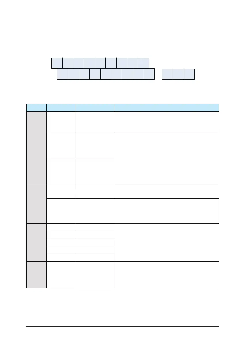
Figure 3-15 Arrangement of control circuit terminals
+10V
COM
GND
GND AO1
FM
DO1 CME COM
OP +24V
T/A
1A I 2A I 1D I
2D I
3D I
4D I
5D I
/
T
B
/
T
C
The functions of the terminals of the control circuit are described as follows:
Table 3-4 Description of functions of the control circuit terminals
Type Terminal Name Function Description
Power
supply
+10V-GND
External +10 V power
supply
Provides a +10 V power supply to an external unit
Generally used to supply an external potentiometer of 1 to 5 kΩ
Max. output current: 10 mA
+24V-COM
External +24V power
supply
Provides a +24V power supply to an external unit
Generally used to supply the DI/DO terminals and external
sensors
Max. output current: 200mA
OP
Input terminals of
external power supply
Connect to +24 V by default
When DI1 to DI5 need to be driven by external signals, OP
must be disconnected from +24 V and connected to an external
power supply.
Analog
inputs
AI1-GND Analog input 1
1. Voltage range for inputs: 0 to 10 VDC
2. Input resistance: 22 kΩ
AI2-GND Analog input 2
1. Either a voltage or a current input, determined by the
selection of jumper J8.
Input range: 0 to 10 VDC or 40 20 mA
Input resistance: 22 kΩ (voltage input), 500 Ω (current input)
Digital
inputs
DI1- OP Digital input 1
1. Optically-coupled isolation compatible with dual-polarity inputs
2. Input resistance: 2.4 kΩ
3. Voltage range for level inputs: 9 to 30 V
DI2- OP Digital input 2
DI3- OP Digital input 3
DI4- OP Digital input 4
DI5- OP Digital input 5
Analog
output
AO1-GND Analog output 1
Either a voltage or a current output, determined by selection of
jumper J5.
Output voltage range: 0 to 10 V
Output current range: 0 to 20mA
 Loading...


