Chapter 5 Function Code Table
- 81 -
Function
Code
Parameter Name Description
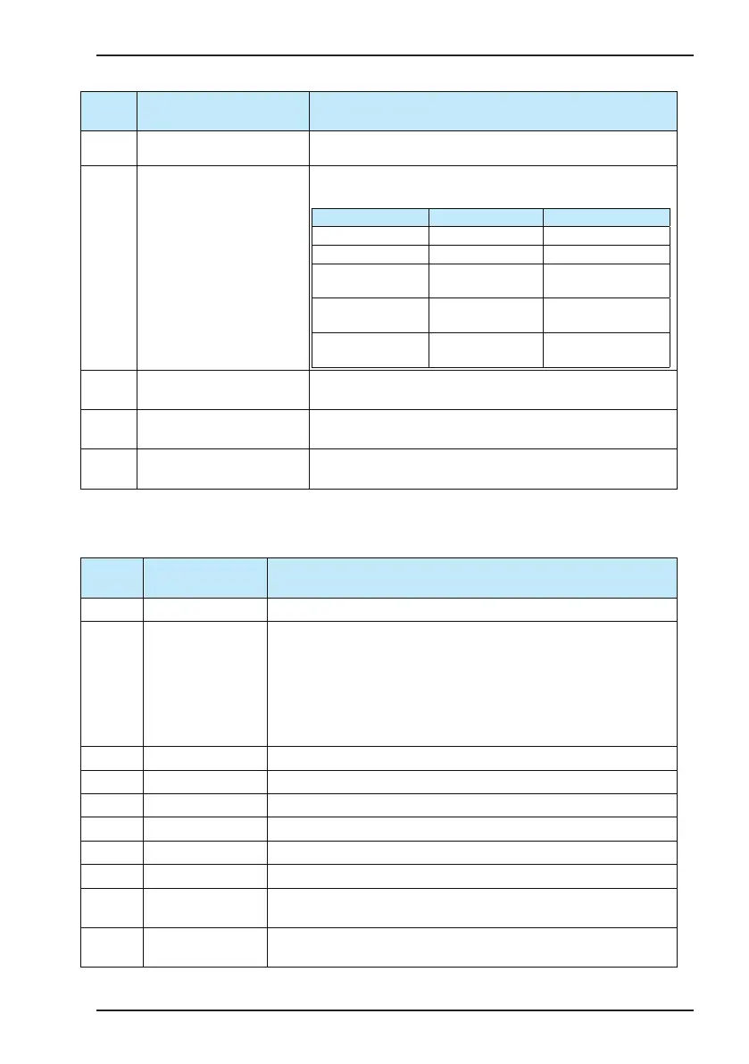
E*.12 Running step at fault occurrence
It records the running step of the AC drive at fault occurrence. For the
display, see U0.26.
E*.13 Control mode at fault occurrence
It records the setting value of command source, frequency reference
setting channel and control mode at fault occurrence.
Digit Meaning Description
Ten thousand's digit Reserved
Thousand's digit Reserved
Hundred's digit Command source
For the data meaning,
refer to bF.04.
Ten's digit
Frequency reference
setting channel
For the data meaning,
refer to A0.07.
Unit's digit Drive control mode
For the data meaning,
refer to b1.00.
E*.14
Internal variable at fault
occurrence
Reserved
E*.15
Synchronous frequency at fault
occurrence
It records the instantaneous value of synchronous frequency at fault
occurrence.
E*.16
Brake pipe current at fault
occurrence
It records the instantaneous current of the brake pipe at occurrence of
brake pipe overload (15#).
Groups U0 and U1 display the real-time monitor information of the AC drive. Group U0 parameters are refreshed in
real time and non-retentive at power down. Group U1 parameters display the accumulative calculation information
and are retentive at power down
Function
Code
Parameter Name Description
U0.00 Frequency reference It displays the current frequency reference of the AC drive.
U0.01 Feedback frequency
It displays the the feedback value of the actual motor running frequency. It is
the feedback frequency calculated by the AC drive if the drive runs without an
encoder. It is the actual motor running frequency fed back by the encoder if the
drive runs with an encoder.
If you cannot judge whether the encoder works properly during onsite
commissioning, check whether the value of this parameter is normal in V/F mode.
If yes, the encoder fault is eliminated.
U0.02 Target frequency It displays the frequency the AC drive will reach nally.
U0.03 Output current It displays the output current of the AC drive during running.
U0.04 Output voltage It displays the output voltage of the AC drive during running.
U0.05 Output power It displays the output power of the AC drive during running.
U0.06 Output torque It displays the output torque of the AC drive during running.
U0.07 Bus voltage It displays the bus voltage of the AC drive.
U0.08 Current load weight
It displays the actual load weight of the current elevator detected by the weighing
sensor.
U0.10 DI state
It displays the state of DI terminals. The display method is the same as that
described in E*.08 to E*.11.
 Loading...


