Chapter 5 Function Code Table
- 80 -
Groups E0 and EF display the fault information. Each group of parameters indicate the information of a fault. Group E0
displays the information about the latest fault, and group EF displays the information of the earliest fault. The display in
each group is the same. Parameters in groups E0 to EF cannot be modied and are retentive at power down.
Function
Code
Parameter Name Description
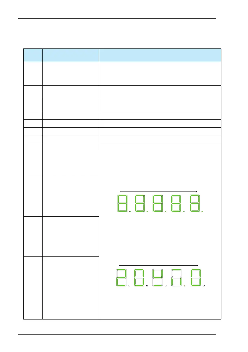
E*.00 Fault code
The ve-digit LED data display is numbered 5, 4, 3, 2, 1 from left to the
right. For example, the display is 104.01. 5#, 4# and 3# constitute the fault
code, amongst which 5# indicates the fault level, 4# and 3# indicate the
fault code. 2# and 1# indicate the fault sub-code and are reserved.
E*.01
Frequency reference at fault
occurrence
It monitors the display value of U0.00 at fault occurrence.
E*.02
Feedback frequency at fault
occurrence
It monitors the display value of U0.01 at fault occurrence (U0.00 in V/F
control).
E*.03 Output current at fault occurrence It monitors the display value of U0.03 at fault occurrence.
E*.04 Output voltage at fault occurrence It monitors the display value of U0.04 at fault occurrence.
E*.05 Output power at fault occurrence It monitors the display value of U0.05 at fault occurrence.
E*.06 Output torque at fault occurrence It monitors the display value of U0.06 at fault occurrence.
E*.07 Bus voltage at fault occurrence It monitors the display value of U0.07 at fault occurrence.
E*.08
State of input functions 1 to 16 at
fault occurrence
These four parameters display the state of input/output functions. Each
function code indicates the state of 16 input/output functions by bits. After
you enter the function code menu, the function code displays the decimal
value. Press the UP key to enter the user viewing mode.
The ve-digit LED data display is numbered 5, 4, 3, 2, 1 from left to the
right.
A
B
C
D
E
F
G
DP
A
B
C
D
E
F
G
DP
A
B
C
D
E
F
G
DP
A
B
C
D
E
F
G
DP
LED5 LED4 LED3 LED2
5
4 3
2
A
B
C
D
E
F
G
DP
LED1
1
After entering the user viewing mode, LEDs 5 and 4 indicate the No. of
the currently viewed input/output function. LED1 indicates whether the
currently viewed function is active (0: inactive; 1: active). You can press the
UP or DOWN key to increase or decrease the function No.
LEDs 2 and 3 display the state of all 16 functions by segment. To be
specic, the rst eight functions correspond to segments A to DP of LED2,
and the last eight functions correspond to segments A to DP of LED3.
A
B
C
D
E
F
G
DP
A
B
C
D
E
F
G
DP
A
B
C
D
E
F
G
DP
A
B
C
D
E
F
G
DP
LED5 LED4 LED3 LED2
5
4 3
2
A
B
C
D
E
F
G
DP
LED1
1
In this gure, LEDs 5 and 4 indicate the state of input function 20. This
function is inactive (LED1 is 0). Amongst the input functions 17 to 32,
functions 17, 19, 21, 24, 26, 28, 30 and 31 are active and the other
functions are inactive (LEDs 2 and 3).
E*.09
State of input functions 17 to 32 at
fault occurrence
E*.10
State of input functions 33 to 48 at
fault occurrence
E*.11
State of output functions 1 to 16 at
fault occurrence
 Loading...


