Chapter 8 Maintenance and Troubleshooting
- 114 -
8.3 Trouble-shooting
The CS200 monitors all input signals, running conditions, and external feedback information. Once a fault occurs,
the AC drive performs protection and meanwhile the operation panel displays the fault code.
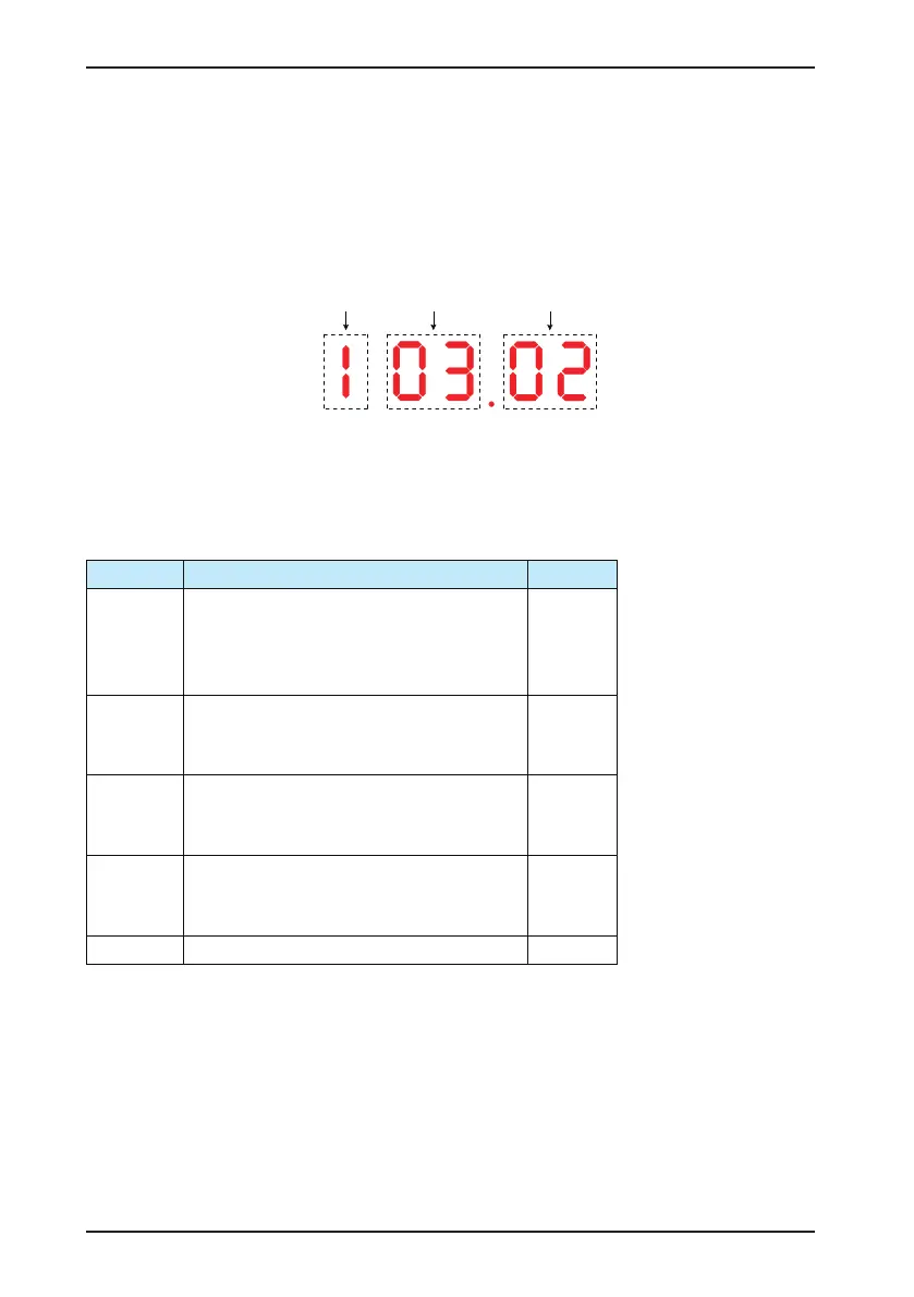
The ve-digit LED data display is numbered 5, 4, 3, 2, 1 from left to the right, amongst which 5# indicates the fault
level, 4# and 3# indicate the fault code, and 2# and 1# indicate the fault sub-code and are reserved. For example,
the display is 103.02 as shown in the following gure.
Fault level Fault code
Fault sub-code
Before contacting Inovance for technical support, you can rst determine the fault type, analyze the causes, and
perform troubleshooting according to the following tables.
The CS200 is the core of the entire electrical control system of the elevator construction. The fault information of
the CS200 is classied into ve levels. The AC drive performs different actions for different fault levels, as listed in
the following table.
Fault Level Action Display
Level 1
Display fault code.
Disable output function 1 (Brake control).
Enable output function 2 (Stop upon fault).
Perform the operation of coasting to stop.
Er1**
Level 2
Display fault code.
Enable output function 3 (Alarm upon fault).
Perform the operation of quick stop.
Er2**
Level 3
Display fault code.
Enable output function 3 (Alarm upon fault).
Perform the operation of decelerating to stop.
Er3**
Level 4
Display fault code.
Enable output function 4 (Fault prompt).
The working condition is not affected.
Er4**
Level 5 The working condition is not affected. None
Note: Faults 1# to 40# are the drive performance faults and are considered level 1 faults by default. These faults
cannot be modied.
Faults 41# to 65# are the drive function faults, and you can modify the level of these faults in bF.10 to bF.14. For
details, see the descriptions of bF.10 to bF.14.
 Loading...


