Goodrive350 series high-performance multi-function inverter Chapter 5
-114-
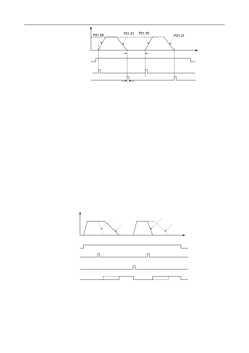
Frequency
Positioning
speed
Running command
Cyclic positioning
enable signal terminal
Positioning completion signal
P21.22 Hold time
of positioning arrival
Time
P21.25 Hold time of positioning completion signal
Step 1–4: These four steps are the same with the first four steps of the commissioning procedures for
closed-loop vector control, which aim to fulfill the control requirements of closed-loop vector control.
Step 5: Set P21.00=0011 to enable digital positioning. Set P21.17, P21.11 and P21.12 (set
positioning displacement) according to actual needs ; set P21.18 and P21.19 (set positioning speed);
set P21.20 and P21.21 (set acceleration/deceleration time of positioning).
Step 6: Single positioning operation
Set P21.16.bit1=0, and the motor will carry out single positioning action and stay in the positioning
position according to the setup in step 5.
Step 7: Cyclic positioning operation
Set P21.16.bit1=1 to enable cyclic positioning. The cyclic positioning is divided into continuous mode
and repetitive mode; users can also carry out cyclic positioning through terminal function (no. 55,
enable digital positioning cycle)
6. Commissioning procedures for positioning of photoelectric switch
Photoelectric switch positioning is to realize positioning function based on closed-loop vector control.
Directdeceleration positioning
Frequency
Running command
Photoelectric switch
arrival signal
Cyclic positioning
enable signal
Positioning completion
signal
Constant speed+
deceleration positioning
Directdeceleration positioning
Constant speed+
deceleration positioning
Time
Step 1–4: These four steps are the same with the first four steps of the commissioning procedures for
closed-loop vector control, which aim to fulfill the control requirements of closed-loop vector control.
Step 5: Set P21.00=0021 to enable photoelectric switch positioning, the photoelectric switch signal
can be connected to S8 terminal only, and set P05.08=43, meanwhile, set P21.17, P21.11 and
 Loading...

