Goodrive350 series high-performance multi-function inverter Appendix A
-290-
power supply are properly connected.
It blinks when the communication card is in the
pre-operation state.
It blinks once when the communication card is in
the stopped state.
This indicator is on when the CAN controller bus
is off or a fault occurs on the inverter.
It is off when the communication card is in the
working state.
It blinks when the address setting is incorrect.
It blinks once when a received frame is missed
or an error occurs during frame receiving.
For details about the operation, see the Goodrive350 Series Inverter Communication Extension Card
Operation Manual.
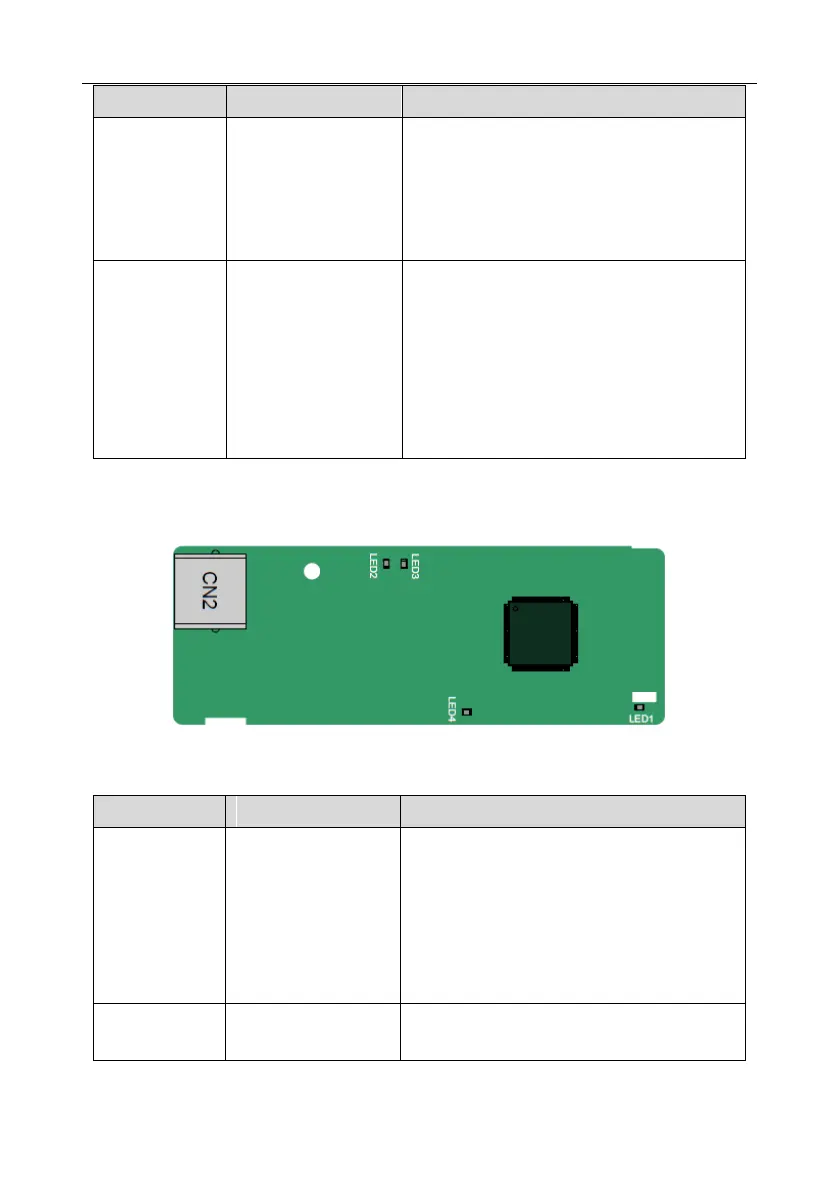
A.6.3 Ethernet communication card––EC-TX504
The EC-TX504 communication card adopts standard RJ45 terminals.
Indicator definition
This indicator is on when the extension card is
establishing a connection with the control board;
it blinks periodically after the extension card is
properly connected to the control board (the
period is 1s, on for 0.5s, and off for the other
0.5s); and it is off when the extension card is
disconnected from the control board.
This indicator is on after the control board feeds
power to the communication card.
 Loading...

