Goodrive350 series high-performance multi-function inverter Appendix A
-285-
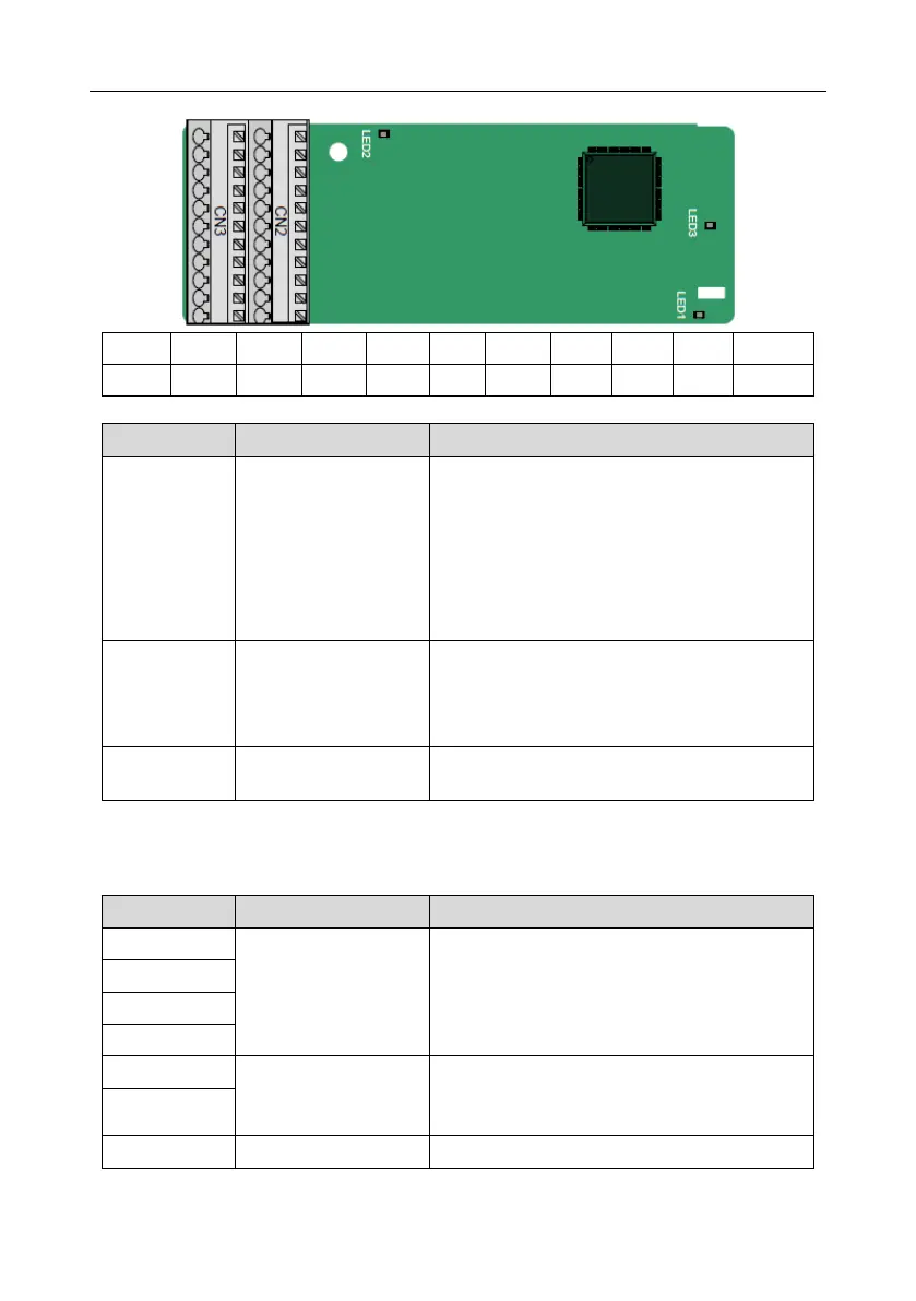
A.5.3 Resolver PG card––EC-PG504-00
Indicator definition
This indicator is on when the extension card is
establishing a connection with the control board; it
blinks periodically after the extension card is
properly connected to the control board (the
period is 1s, on for 0.5s, and off for the other
0.5s); and it is off when the extension card is
disconnected from the control board.
This indicator is off when the encoder is
disconnected; it is on when the encoder signals
are normal; and it blinks when the encoder signals
are not stable.
This indicator is on after the control board feeds
power to the PG card.
The EC-PG504-00 extension card can be used in combination with a resolver of excitation voltage 7
Vrms. It is user-friendly, adopting spring terminals.
EC-PG504-00 terminal function description
Recommended resolver transformation ratio: 0.5
Encoder excitation
signal
1. Factory setting of excitation: 10 kHz
2. Supporting resolvers with an excitation voltage
of 7 Vrms
1. Differential input of 5 V
 Loading...

