Goodrive350 series high-performance multi-function inverter Chapter 5
-88-
Detailed parameter description
Corresponding HDO output of
lower limit
Upper limit of HDO output
Corresponding HDO output of
upper limit
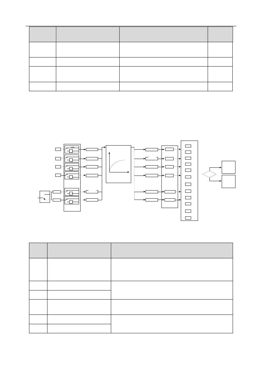
5.5.11 Digital input
GD350 series inverter carries four programmable digital input terminals and two HDI input terminals.
The function of all the digital input terminals can be programmed by function codes. HDI input
terminal can be set to act as high-speed pulse input terminal or common digital input terminal; if it is
set to act as high-speed pulse input terminal, users can also set HDIA or HDIB high-speed pulse input
to serve as the frequency reference and encoder signal input.
S1
S2
S3
S4
HDIA
HD1B
P05.08 (input terminal polarity)
P05.01
P05.02
P05.03
P05.04
T delay
T delay
T delay
T delay
T delay
T delay
P05.13
P05.15
P05.17
P05.19
P05.21
P05.23
0
1
2
3
4
5
.
.
.
.
29
30
P05.09 (digital filter time)
(Default value is 1)
(Default value is 4)
(Default value is 7)
(Default value is 0)
(Default value is 0)
(Default value is 0)
P05.00
(HDI input type)
0
1
0
1
-1
0
1
-1
0
1
-1
0
1
-1
0
1
-1
0
1
-1
P17.11
Digital input
terminal state
P07.39
Input terminal
state of present
fault
Fault?
Fault
Run
Digital function selection
T delay
T delay
T delay
T delay
T delay
T delay
P05.12
P05.14
P05.16
P05.18
P05.20
P05.22
P05.05
P05.06
This parameter is used to set the corresponding function of digital multi-function input terminals.
Note: Two different multi-function input terminals cannot be set to the same function.
The inverter does not act even if there is signal input;
users can set the unused terminals to "no function" to
avoid misacts.
Control the forward/reverse running of the inverter by
external terminals.
Set the inverter running mode to tri-line control mode by
this terminal. See P05.13 for details.
Frequency when jogging, see P08.06, P08.07 and
P08.08 for jogging acceleration/deceleration time.
 Loading...

