Goodrive350 series high-performance multi-function inverter Chapter 5
-37-
5.3 Keypad display
The display state of GD350 series keypad is divided into stop state parameter display, running state
parameter display and fault alarm state display.
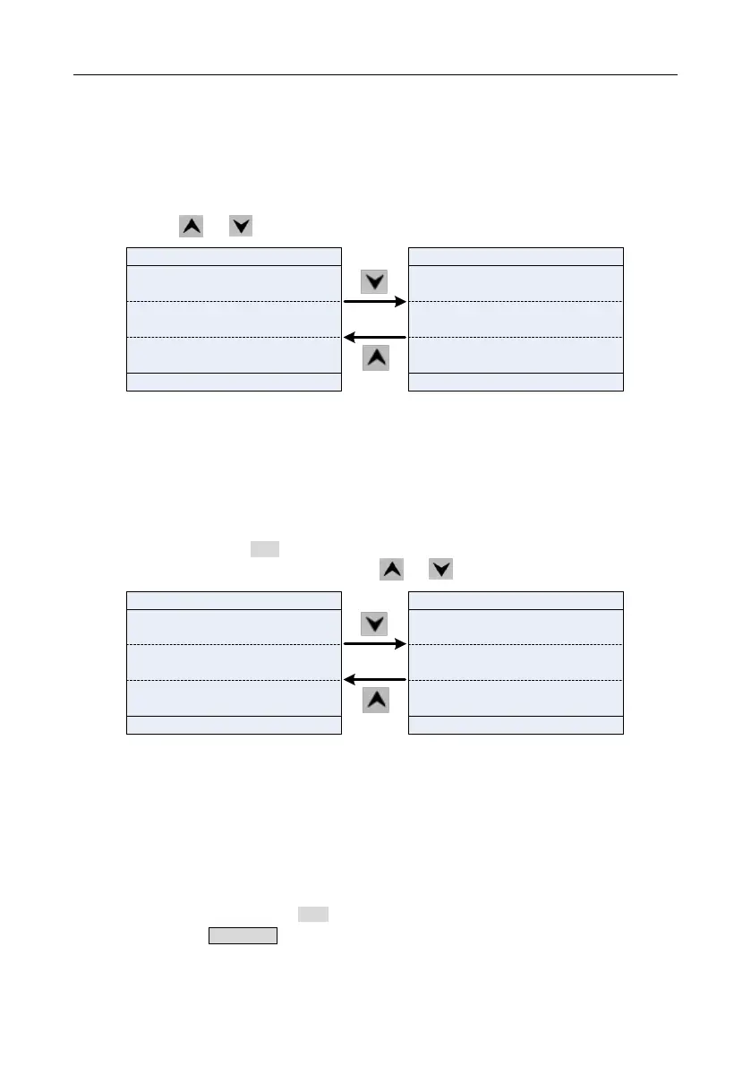
5.3.1 Stop parameter display state
When the inverter is in stop state, the keypad displays stop state parameters, and this interface is the
main interface during power-up by default. Under stop state, parameters in various states can be
displayed. Press or to shift the displayed parameter up or down.
01: GD350
16:02:35
Forward
Local Ready
Set frequency
P17.00 Hz
50.00
DC bus voltage
P17.11 V
540.0
0x0000
AboutMonitoring
Menu
Digital input terminal state
P17.12
16:02:35
DC bus voltage
P17.11 V
540.0
Digital input terminal state
P17.12
0x0000
0x0000
Digital output terminal state
P17.13
01: GD350
Forward
Local Ready
AboutMonitoring
Menu
Fig 5.3 Stop parameter display state
The stop display parameter list is defined by the user, and each state variable function code can be
added to the stop display parameter list as needed. The state variable which has been added to the
stop display parameter list can also be deleted or shifted.
5.3.2 Running parameter display state
After receiving valid running command, the inverter will enter running state, and the keypad displays
running state parameter with RUN indicator on the keypad turning on. Under running state, multiple
kinds of state parameters can be displayed. Press or to shift up or down.
01: GD350
16:02:35
Output frequency
P17.01 Hz
50.00
Set frequency
P17.00 Hz
50.00
540.0
DC bus voltage
P17.11 V
01: GD350
16:02:35
Set frequency
P17.00 Hz
50.00
DC bus voltage
P17.11 V
540.0
378
Output voltage
P17.03 V
Forward
Local Run
Forward
Local
Run
AboutMonitoring
Menu
AboutMonitoring
Menu
Fig 5.4 Running parameter display state
Under running state, multiple kinds of state parameters can be displayed. The running display
parameter list is defined by the user, and each state variable function code can be added to the
running display parameter list as needed. The state variable which has been added to the running
display parameter list can also be deleted or shifted.
5.3.3 Fault display state
The inverter enters fault alarm display state once fault signal is detected, and the keypad displays
fault code and fault information with TRIP indicator on the keypad turning on. Fault reset operation
can be carried out via STOP/RSTkey, control terminal or communication command.
The fault code will be kept displaying until fault is removed.
 Loading...

