Goodrive350 series high-performance multi-function inverter Appendix B
-296-
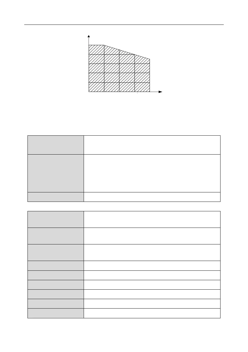
details about the derating, see the following figure.
Derating coefficient (%)
100
80
60
40
20
0
1000 2000 3000 4000
Altitude (m)
B.2.2.3 Derating due to carrier frequency
The power of Goodrive350 series inverters varies according to carrier frequencies. The rated power
of an inverter is defined based on the carrier frequency set in factory. If the carrier frequency exceeds
the factory setting, the power of the inverter is derated by 10% for each increased 1 kHz.
B.3 Grid specifications
AC 3PH 380V (-15%)–440V (+10%)
AC 3PH 520V (-15%)–690V (+10%)
According to the definition in IEC 60439-1, the maximum allowable
short-circuit current at the incoming end is 100 kA. Therefore, the
inverter is applicable to scenarios where the transmitted current in
the circuit is no larger than 100 kA when the inverter runs at the
maximum rated voltage.
50/60 Hz±5%, with a maximum change rate of 20%/s
B.4 Motor connection data
asynchronous induction motor or permanent-magnet synchronous
motor
0–U1 (rated voltage of the motor), 3PH symmetrical, Umax (rated
voltage of the inverter) at the field-weakening point
The short-circuit protection for the motor output meets the
requirements of IEC 61800-5-1.
1.5 times of the rated power of the motor
 Loading...

