EasyManuals Logo
Home>INVT>DC Drives>Goodrive350 Series

INVT Goodrive350 Series User Manual

INVT Goodrive350 Series
341 pages
To Next Page IconTo Next Page
To Previous Page IconTo Previous Page
Page #296 background imageLoading...
Page #296 background image
Goodrive350 series high-performance multi-function inverter Appendix A
-291-
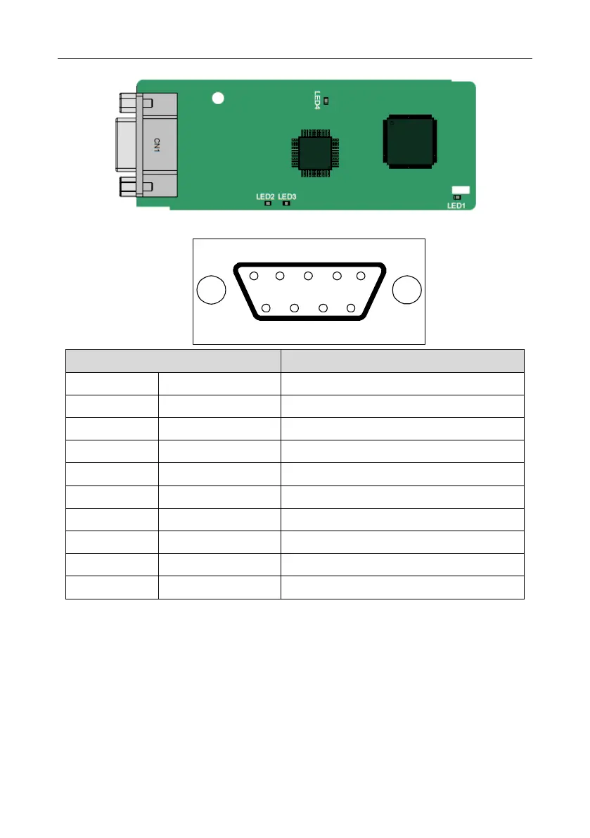
A.6.4 PROFIBUS-DP communication card––EC-TX503
CN1 is a 9-pin D-type connector, as shown in the following figure.
5
4 3
2 1
9 8 7 6
Connector pin
Description
1
-
Unused
2
-
Unused
3
B-Line
Data+ (twisted pair 1)
4
RTS
Request sending
5
GND_BUS
Isolation ground
6
+5V BUS
Isolated power supply of 5 V DC
7
-
Unused
8
A-Line
Data- (twisted pair 2)
9
-
Unused
Housing
SHLD
PROFIBUS cable shielding line
+5V and GND_BUS are bus terminators. Some devices, such as the optical transceiver (RS485),
may need to obtain power through these pins.
On some devices, the transmission and receiving directions are determined by RTS. In normal
applications, only A-Line, B-Line, and the shield layer need to be used.

Table of Contents

Questions and Answers:

Question and Answer IconNeed help?

Do you have a question about the INVT Goodrive350 Series and is the answer not in the manual?

INVT Goodrive350 Series Specifications

General IconGeneral
BrandINVT
ModelGoodrive350 Series
CategoryDC Drives
LanguageEnglish

Related product manuals