Goodrive350 series high-performance multi-function inverter Chapter 9
-246-
1# 2
#
3 # 4 # 32 #
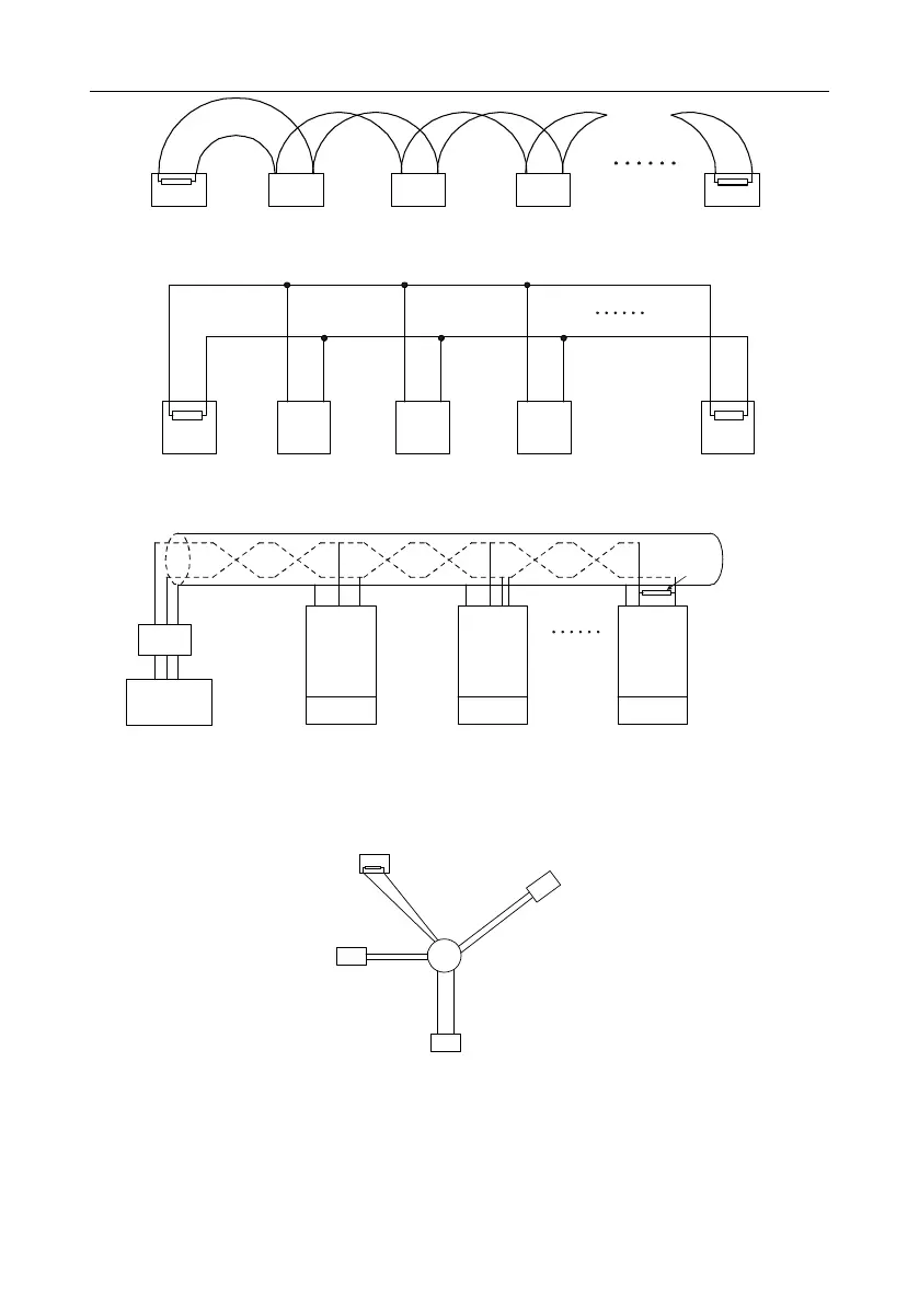
120Ω
120Ω
Fig 9.2 On-site chrysanthemum connection diagram
1# 2# 3# 31#Master
A+
B-
A+ B-
Fig 9.3 Simplified chrysanthemum connection diagram
INVT
inverter
Address 1
Earth
485+
485-
485+
485-
485+
485-
120Ω
Terminal resistor
PC
Converter
GND
RS232-RS485
Max. length of the
cable: 15 m
Shielded twisted pair
Address 2 Address N
INVT
inverter
INVT
inverter
Earth Earth
Fig 9.4 Practical application diagram of chrysanthemum connection
Fig 9.5 shows the start connection diagram. When this connection mode is adopted, the two devices
that are farthest away from each other on the line must be connected with a terminal resistor (in Fig
9.5, the two devices are devices 1# and 15#).
1#
15#
32#
6
#
Main control
device
Fig 9.5 Star connection
Use shielded cable, if possible, in multi-device connection. The baud rates, data bit check settings,
and other basic parameters of all the devices on the RS485 line must be set consistently, and
addresses cannot be repeated.
 Loading...

