Goodrive350 series high-performance multi-function inverter Chapter 5
-75-
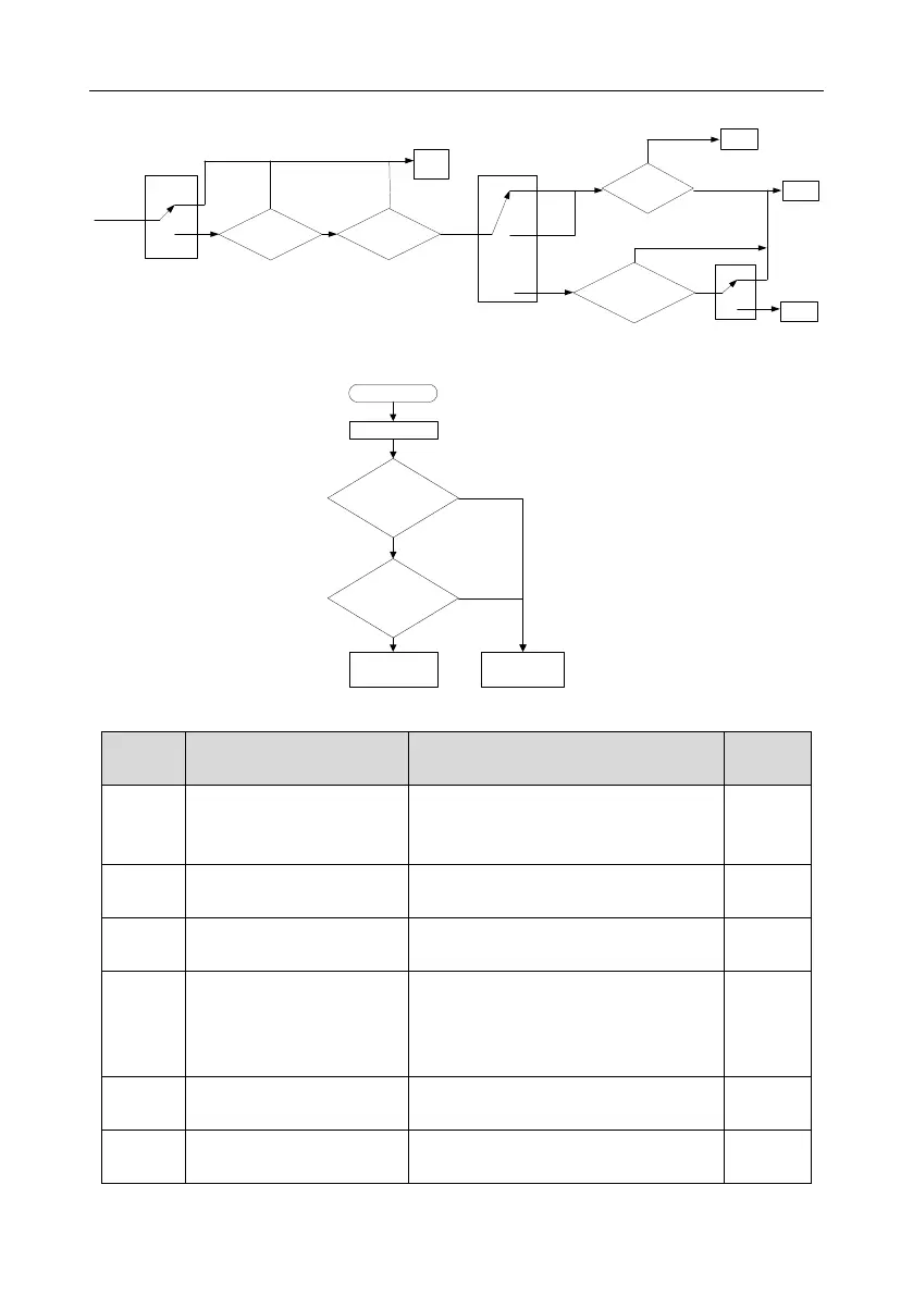
2. Logic diagram for restart after power-cut
Standby
The running state
before power cut
0
1
P01.21
(restart at power-cut)
Waiting time of restart at
power-cut>P01.22
0
1
2
Stop
Run
0
1
P01.18
(Power-on terminal running protection
selection)
Delay time of restart
>P01.123
N
Y
Y
N
Restart after
power-cut
Run
Stop
FWD/REV
Whether running terminal
command is valid
N
Run
Y
P00.01
Running command channel
Keypad
Communi
cation
Termin
al
3. Logic diagram for restart after automatic fault reset
Inverter fault
In running
Automatic reset times
of inverter fault<P08.28
Automatic reset
interval of inverter
fault>P08.29
Inverter fault reset,
start running
Display fault
code, and stop
N
N
Y
Y
Related parameter list:
Detailed parameter description
0: Keypad
1: Terminal
2: Communication
0: Direct start
1: Start after DC brake
2: Start after speed-track 1
3: Start after speed-track 2
Starting frequency of direct
start
Hold time of starting
frequency
 Loading...

