Goodrive350 series high-performance multi-function inverter Appendix D
-314-
reduces grounding resistance, and thus improves impedance continuity.
To effectively restrict the emission and conduction of radio frequency (RF) interference, the
conductivity of the shielded cable must at least be 1/10 of the conductivity of the phase conductor.
This requirement can be well met by a copper or aluminium shield layer. The following figure shows
the minimum requirement on motor cables of an inverter. The cable must consist of a layer of
spiral-shaped copper strips. The denser the shield layer is, the more effectively the electromagnetic
interference is restricted.
Cross-section of the cable
Insulating layer
Shield layer
D.4.2 Control cables
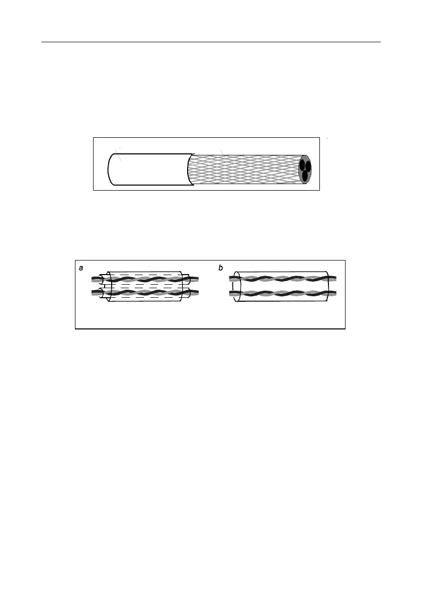
All analog control cables and cables used for frequency input must be shielded cables. Analog signal
cables need to be double-shielded twisted-pair cables (as shown in figure a). Use one separate
shielded twisted pair for each signal. Do not use the same ground wire for different analog signals.
Power cable arrangement
Multiple double-shielded twisted-pair cables
Multiple shielded twisted-pair cables
For low-voltage digital signals, double-shielded cables are recommended, but shielded or unshielded
twisted pairs (as shown in figure b) also can be used. For frequency signals, however, only shielded
cables can be used.
Relay cables need to be those with metal braided shield layers.
Keypads need to be connected by using network cables. In complicated electromagnetic
environments, shielded network cables are recommended.
Note: Analog signals and digital signals cannot use the same cables, and their cables must be
arranged separately.
Do not perform any voltage endurance or insulation resistance tests, such as high-voltage insulation
tests or using a megameter to measure the insulation resistance, on the inverter or its components.
Insulation and voltage endurance tests have been performed between the main circuit and chassis of
each inverter before delivery. In addition, voltage limiting circuits that can automatically cut off the test
voltage are configured inside the inverters.
Note: Check the insulation conditions of the input power cable of an inverter according to the local
 Loading...

