Goodrive350 series high-performance multi-function inverter Appendix D
-329-
brake usage. You can select the brake system based on the actual operation conditions.
3. When using an external brake unit, set the brake voltage class of the brake unit properly by
referring to the manual of the dynamic brake unit. If the voltage class is set incorrectly, the
inverter may not run properly.
Do not use brake resistors whose resistance is lower than the specified
minimum resistance. Inverters do not provide protection against overcurrent
caused by resistors with low resistance.
In scenarios where brake is frequently implemented, that is, the brake usage
is greater than 10%, you need to select a brake resistor with higher power as
required by the operation conditions according to the preceding table.
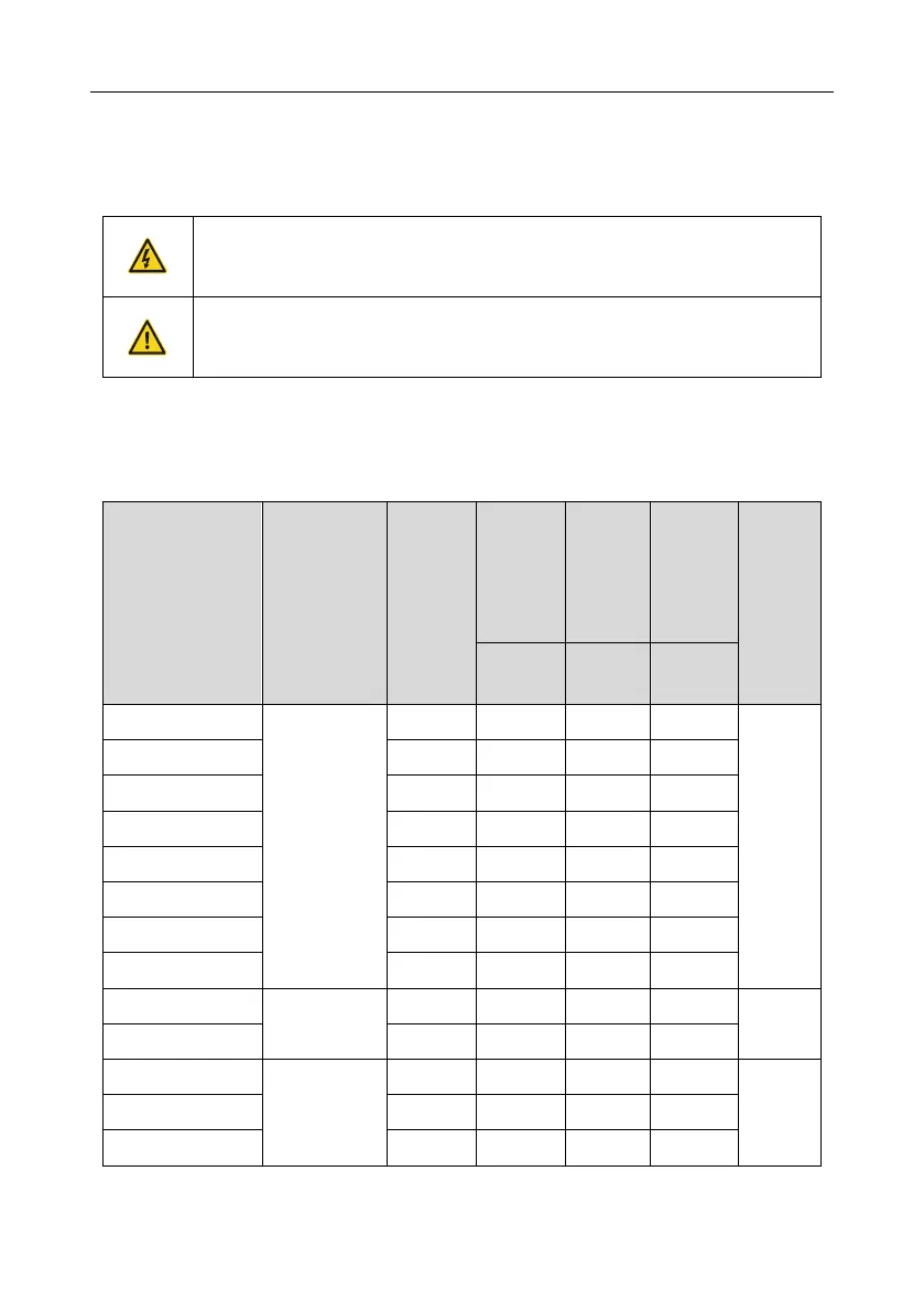
D.8.1.2 Brake units for AC 3PH 520V (-15%)–690V (+10%)
External brake units need to configured for Goodrive350 series inverters of 660 V. Select brake
resistors according to the specific requirements (such as the brake torque and brake usage
requirements) on site.
Resistance
applicable
for 100%
brake
torque (Ω)
Dissipated
power of
brake
resistor
(kW)
Dissipated
power of
brake
resistor
(kW)
Dissipated
power of
brake
resistor
(kW)
Min.
allowable
brake
resistance
(Ω)
 Loading...

