Goodrive350 series high-performance multi-function inverter Chapter 9
-245-
Max. transmission
distance
Max. transmission
distance
When RS485 interfaces are used for long-distance communication, it is recommended that you use
shielded cables, and use the shield layer as the ground wires.
When there are fewer devices and the transmission distance is short, the whole network works well
without terminal load resistors. The performance, however, degrades as the distance increases.
Therefore, it is recommended that you use a 120 Ω terminal resistor when the transmission distance
is long.
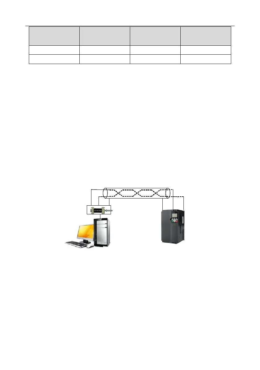
9.3.1.1 Application to one inverter
Fig 9.1 is the Modbus wiring diagram of one inverter and a PC. Generally, PCs do not provide RS485
interfaces, so you need to convert an RS232 interface or USB port of a PC to an RS485 interface.
Connect end A of the RS485 interface to the 485+ port on the terminal block of the inverter, and
connect end B to the 485- port. It is recommended that you use shielded twisted pairs. When an
RS232-RS485 converter is used, the cable used to connect the RS232 interface of the PC and the
converter cannot be longer than 15 m. Use a short cable when possible. It is recommended that you
insert the converter directly into the PC. Similarly, when a USB-RS485 converter is used, use a short
cable when possible.
PC
Inverter
GroundA B
B
A
RS485 line
RS232-RS485 converter
Shielded twisted pair
Ground
485+ 485-
Fig 9.1 Wiring of RS485 applied to one inverter
9.3.1.2 Application to multiple inverters
In practical application to multiple inverters, chrysanthemum connection and star connection are
commonly used.
According to the requirements of the RS485 industrial bus standards, all the devices need to be
connected in chrysanthemum mode with one 120 Ω terminal resistor on each end, as shown in Fig
9.2. Fig 9.3 is the simplified wiring diagram, and Fig 9.4 is the practical application diagram.
 Loading...

