Goodrive350 series high-performance multi-function inverter Chapter 4
-23-
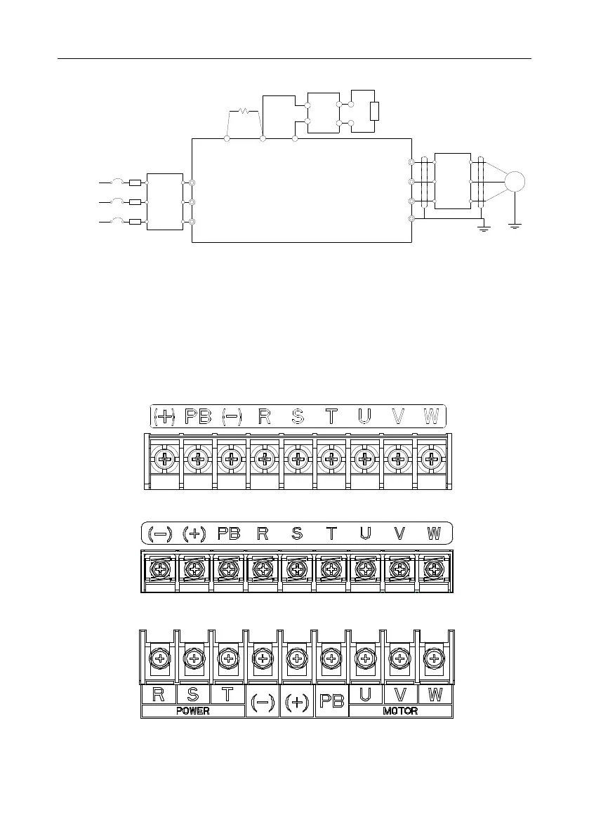
4.3.1.2 AC 3PH 520V(-15%)–690V(+10%) main circuit wiring diagram
R
S
T
W
V
U
PE
M
22kW and above
P1
(+)
DC reactor
3-phase power
660V±15%
50/60Hz
(-)
Input
reactor
Input filter
Fuse
DC-
Brake
resistor
DC+
Brake unit
Output
reactor
Output
filter
Fig 4.8 660V main circuit wiring diagram
Note:
1. The fuse, DC reactor, brake resistor, input reactor, input filter, output reactor and output filter are
optional parts. See Peripheral optional parts for details.
2. P1 and (+) have been short connected by default. If users need to connect to external DC reactor,
take off the short-contact tag of P1 and (+).
3. When connecting the brake resistor, take off the yellow warning sign marked with (+) and (-) on
the terminal block before connecting the brake resistor wire, otherwise, poor contact may occur.
4.3.2 Main circuit terminal diagram
Fig 4.9 3PH 380V 22kW and below
Fig 4.10 3PH 380V 30-37kW
Fig 4.11 3PH 380V 45-110kW
 Loading...

