Goodrive350 series high-performance multi-function inverter Appendix A
-293-
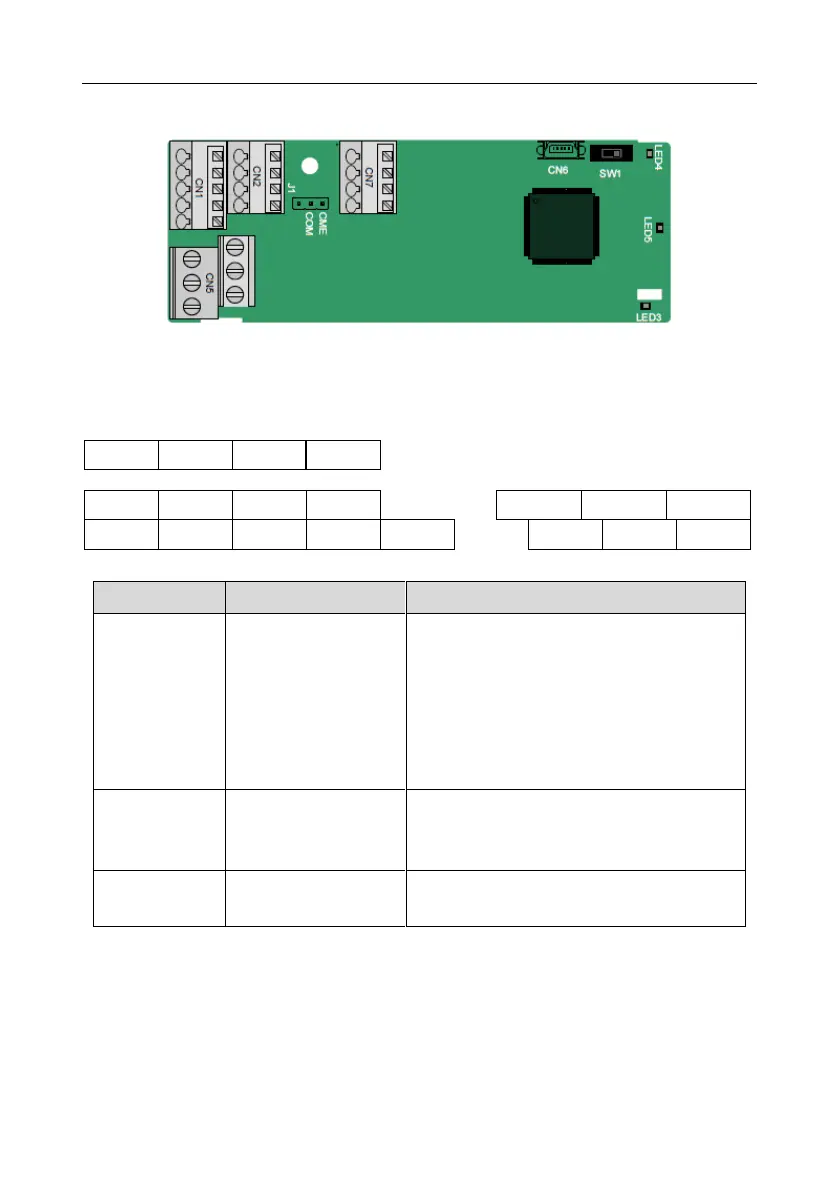
A.7 Programmable extension card function description
A.7.1 Programmable extension card––EC-PC501-00
The terminals are arranged as follows:
SW1 is the start/stop switch of the programmable extension card. CN6 is the program download port,
and you can connect to a computer by using a standard USB cable. COM and CME are shorted
through J1 before delivery.
Indicator definition
This indicator is on when the extension card is
establishing a connection with the control board;
it blinks periodically after the extension card is
properly connected to the control board (the
period is 1s, on for 0.5s, and off for the other
0.5s); and it is off when the extension card is
disconnected from the control board.
PLC running state
indicator
This indicator is on when the DIP switch is
turned to RUN (run the PLC); and it is off when
the switch is turned to STOP (stop the PLC).
This indicator is on after the control board feeds
power to the communication card.
The EC-PC501-00 programmable extension card can replace some micro PLC applications. It adopts
the global mainstream development environment CODESYS, supporting six types of programming
languages, namely the instruction language (IL), structural text (ST), function block diagram (FBD),
ladder diagram (LD), continuous function chart (CFC), and sequential function chart (SFC). It
provides a user program storage space of 128 kB and data storage space of 64 kB, which facilitates
customers' secondary development and meets the customization requirements.
 Loading...

