Goodrive350 series high-performance multi-function inverter Chapter 9
-252-
"LSB of CRC", that is, "MSB of data in 0004H", "LSB of data in 0004H", "MSB of data in 0005H", and
"LSB of data in 0005H".
A piece of data is two bytes, with the MSB on the left and LSB on the right. From the response, we
can see that the data in 0004H is 1388H, and that in 0005H is 0000H.
CRC check occupies two bytes, with the LSB on the left, and MSB on the right.
9.4.2 Command code: 06H, writing a word
This command is used by the master to write data to the inverter. One command can be used to write
only one piece of data. It is used to modify the parameters and operation mode of the inverter.
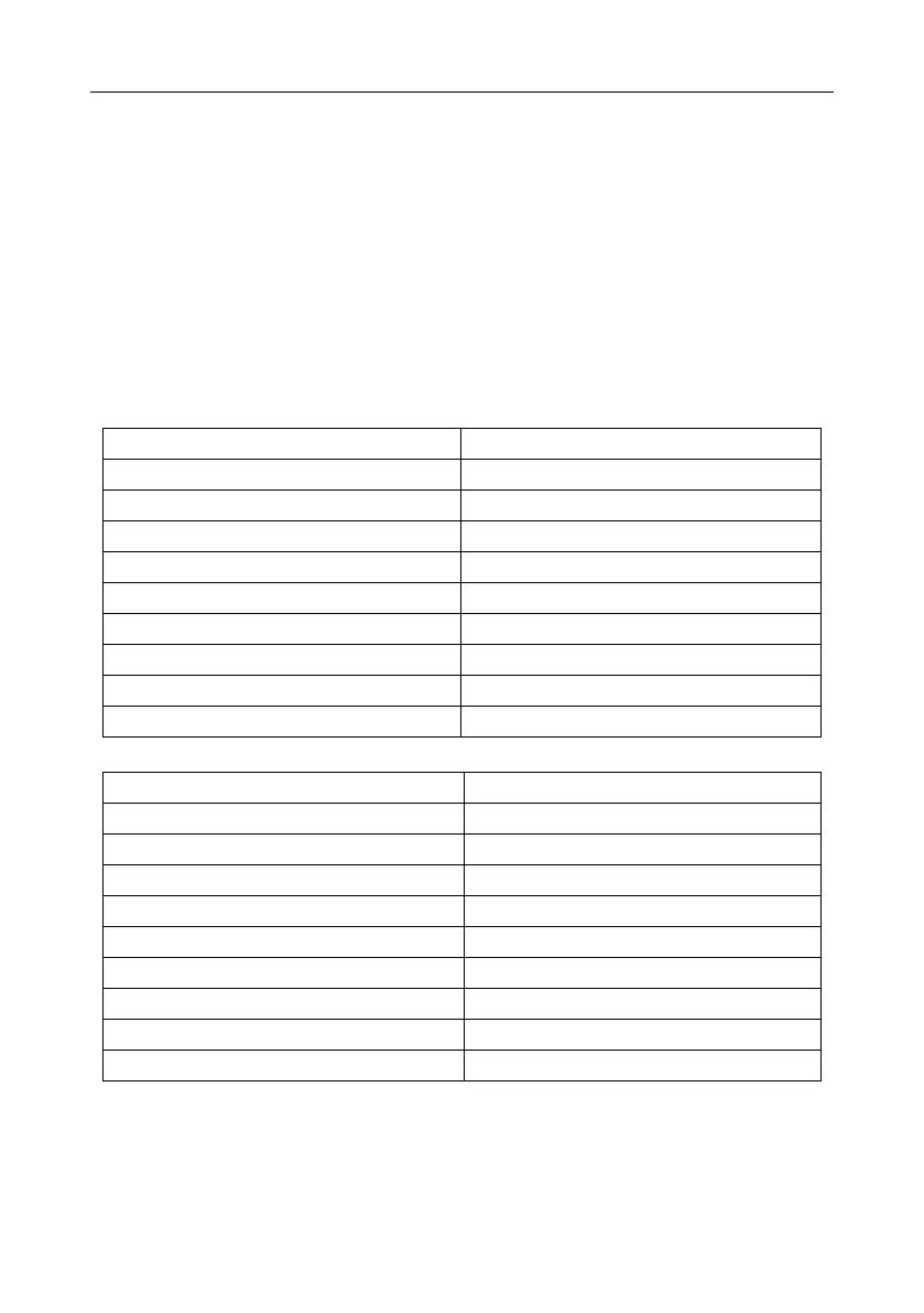
For example, to write 5000 (1388H) to 0004H of the inverter whose address is 02H, the structure of
the frame is described in the following table.
RTU master command (transmitted by the master to the inverter)
T1-T2-T3-T4 (transmission time of 3.5 bytes)
MSB of data writing address
LSB of data writing address
MSB of to-be-written data
LSB of to-be-written data
T1-T2-T3-T4 (transmission time of 3.5 bytes)
RTU slave response (transmitted by the inverter to the master)
T1-T2-T3-T4 (transmission time of 3.5 bytes)
MSB of data writing address
LSB of data writing address
MSB of to-be-written data
LSB of to-be-written data
T1-T2-T3-T4 (transmission time of 3.5 bytes)
Note: The sections 9.2 and 9.3 mainly describes the command formats. For the detailed application,
see the examples in section 9.4.8.
9.4.3 Command code: 08H, diagnosis
Sub-function code description