Goodrive350 series high-performance multi-function inverter Chapter 5
-46-
01: GD350
16:02:35
Forward
Local Ready
P00.00: Speed control mode
P00.01: Running command channel
P00.02: Communication command channel
P00.03: Max. output frequency
P00.04: Upper limit of running frequency
P00.05: Lower limit of running frequency
Max. output frequency Hz
050.00
Max. value: 630.00
Min. value: 50.00
Current value:50.00
Authority: √
Default value: 50.00
Max. output frequency Hz
050.01
Max. value: 630.00
Min. value: 50.00
Current value:50.00
Authority: √
Default value: 50.00
AddReturn
Select
HomepageReturn
Confirm
HomepageReturn
Confirm
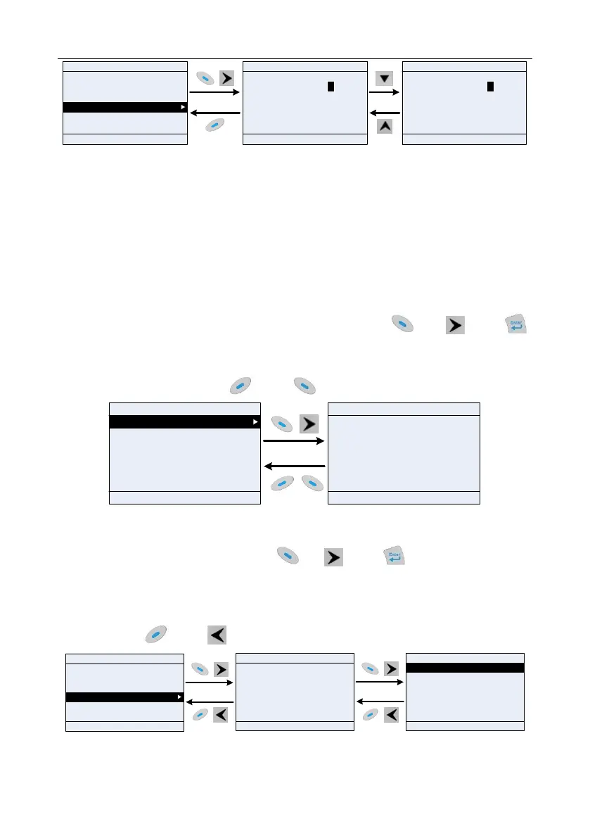
Fig 5.14 Parameter setup edit interface
In parameter selection edit interface, the "authority" on the top right indicates whether this parameter
can be modified or not.
"√" indicates the set value of this parameter can be modified under current state.
"×" indicates the set value of this parameter cannot be modified under current state.
"Current value" indicates the value saved last time.
"Default value" indicates the default value of this parameter.
5.4.7 State monitoring interface
In the fourth-level menu of "state monitoring/fault record" menu, press key, key or
key to enter state monitoring interface. After entering state monitoring interface, the current parameter
value will be displayed in real time, this value is the actually detected value which cannot be modified.
In state monitoring interface, press key or key to return to the previous menu.
HomepageReturn
Confirm
Setting frequency Hz
50.00
Max. value: 630.00
Min. value: 0.0
01: GD350
16:02:35
Forward
Local Ready
01: GD350
16:02:35
Forward
Local Ready
AddReturn
Select
P17.00:Set frequency
P17.01: Output frequency
P17.02: Ramps reference frequency
P17.03: Output voltage
P17.04: Output current
P17.05: Motor speed
Default value: 0.0
Fig 5.15 State monitoring interface
5.4.8 Motor parameter autotuning
In "Motor parameter autotuning" menu, press key, key or key to enter motor
parameter autotuning selection interface, however, before entering motor parameter autotuning
interface, users must set the motor nameplate parameters correctly. After entering the interface,
select motor autotuning type to carry out motor parameter autotuning. In motor parameter autotuning
interface, press key or key to return to the previous menu.
01: GD350
16:02:35
Forward
Local Ready
AddReturn
Confirm
Ensure motor nameplate parameters are set
correctly!
01: GD350
16:02:35
Forward
Local Ready
HomepageReturn
Select
Common parameter setup
Parameter setup
State monitoring/fault record
Motor parameter autotuning
Parameter backup
System setup
HomepageReturn
Confirm
Complete parameter rotary autotuning
Complete parameter static autotuning
Partial parameter static autotuning
01: GD350
16:02:35
Forward
Local Ready
Fig 5.16 Parameter autotuning operation diagram
 Loading...

