Goodrive350 series high-performance multi-function inverter Appendix D
-331-
of hundreds of degrees Celsius. Prevent any materials from coming into
contact with the resistor.
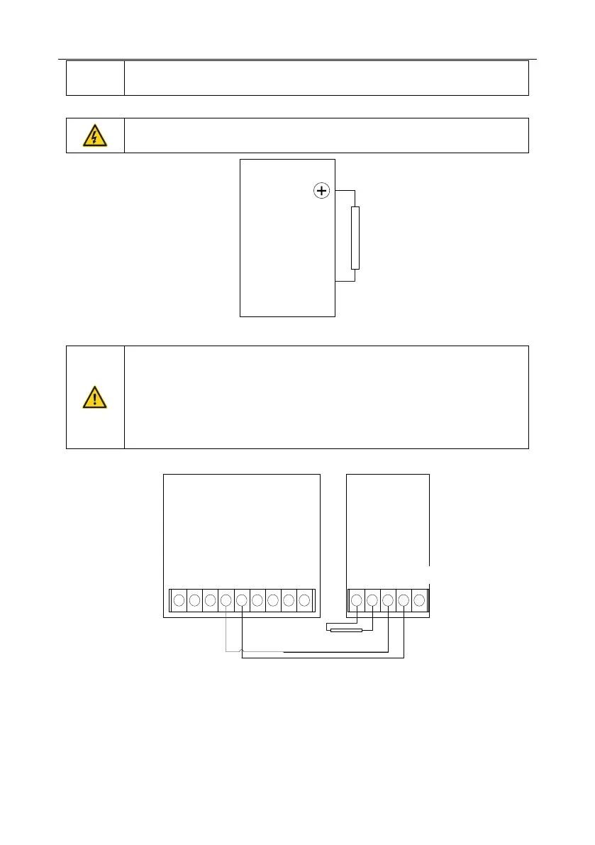
Installation of brake resistors
Inverters of 380 V, 37 kW or lower need only external brake resistors.
PB and (+) are the terminals for connecting brake resistors.
Goodrive350
PB
External brake resistor
Installation of brake units
All inverters of the 660 V series need external brake units.
(+) and (-) are the terminals for connecting brake units.
The connection cables between the (+) and (-) terminals of an inverter and
those of a brake unit must be shorter than 5 m, and the connection cables
between the BR1 and BR2 terminals of a brake unit and the terminals of a
brake resistor must be shorter than 10 m.
The following figure shows the connection of one inverter to a dynamic brake unit.
+ + + + +++
External brake
resistor RB
(+)
DC+
(-)
DC-
BR1 BR2 PE(-)(+)
++ + + + ++
Goodrive350
DBU
brake unit
 Loading...

