Goodrive350 series high-performance multi-function inverter Chapter 9
-263-
If the operation is successful, the following response is returned (same as the command transmitted
by the master):
Parameter
address
CRC
Inverter
address
Write
command
Forward
running
03 06 20 00 00 01 42 28
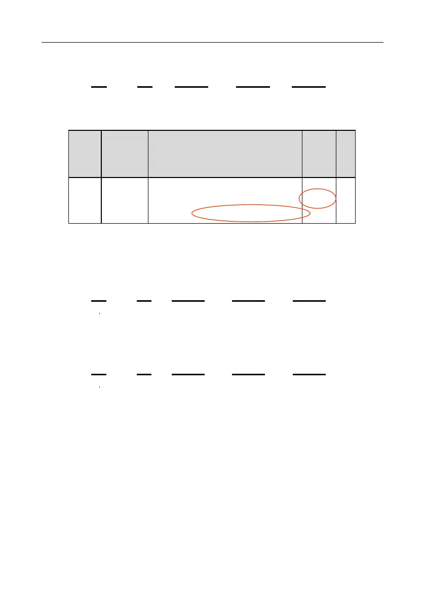
Example 2: Set the "Max. output frequency" of the inverter whose address is 03H to 100 Hz.
Name Detailed parameter description
Used to set the max. output frequency of the
inverter. It isthe basis of frequency setup and the
acceleration/deceleration.
Setting range: Max (P00.04, 10.00) –630.00Hz
From the number of decimals, we can see that the fieldbus scale of the "Max. output frequency"
(P00.03) is 100. Multiply 100 Hz by 100. The value 10000 is obtained, and it is 2710H in the
hexadecimal form.
The command transmitted by the master is as follows:
Parameter
address
Inverter
address
Write
command
CRC
Parameter
data
03 06 00 03 27 10 62 14
If the operation is successful, the following response is returned (same as the command transmitted
by the master):
Parameter
address
Inverter
address
Write
command
CRC
Parameter
data
03 06 00 03 27 10 62 14
Note: In the preceding command description, spaces are added to a command just for explanatory
purposes. In practical applications, no space is required in the commands.
9.4.8.3 Continuously write command 10H examples
Example 1: Set the inverter whose address is 01H to be forward running at the frequency of 10 Hz.
Refer to the table of other function parameters, the address of "Communication-based control
command" is 2000H, 0001H indicates forward running, and the address of "Communication-based
value setting" is 2001H, as shown in the following figure. 10 Hz is 03E8H in the hexadecimal form.
 Loading...

