Goodrive350 series high-performance multi-function inverter Appendix C
-300-
Appendix C Dimension drawings
C.1 What this chapter contains
This chapter describes the dimension drawings of Goodrive350 series inverters. The dimension unit
used in the drawings is mm.
C.2 Keypad structure
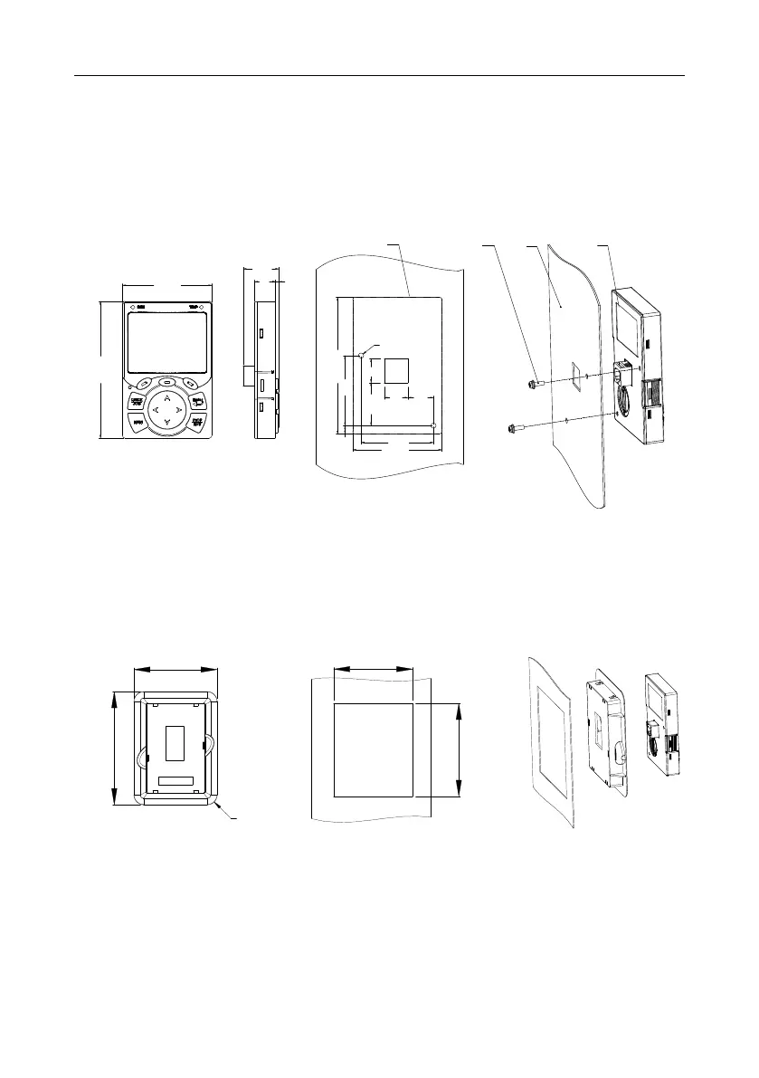
C.2.1 Structure diagram
Installation hole dimensions and diagram for key installation without bracket
Ou
ter outline
of the keypad
2
-
M
3
×
8
tapping
screw
Panel
Keypad
109.3
71.3
28.5
16.8
2.5
109.3
56
6.7
71.3
58
2- ø4
1934.4
19
20.4
Fig C.1 Keypad structure diagram
C.2.2 Keypad installation bracket
Note: When installing an external keypad, you can directly use threaded screws or a keypad bracket.
For inverters of 380 V, 1.5 to 75 kW, you need to use optional keypad installation brackets. For those
of 380 V, 90 to 500 kW and 660 V, 22 to 630 kW, you can use optional brackets or use the standard
keypad brackets externally.
Installation dimensionsKeypad adapter bracket
103
98
140
115
4-R12
Fig C.2 Keypad installation bracket (optional) for inverters of 380 V, 1.5 to 500 kW and 660 V, 22 to
630 kW
 Loading...

