Goodrive350 series high-performance multi-function inverter Chapter 3
-9-
R
S
T
U
V
W
(+)
(-)
DC reactor
P1
PE PE
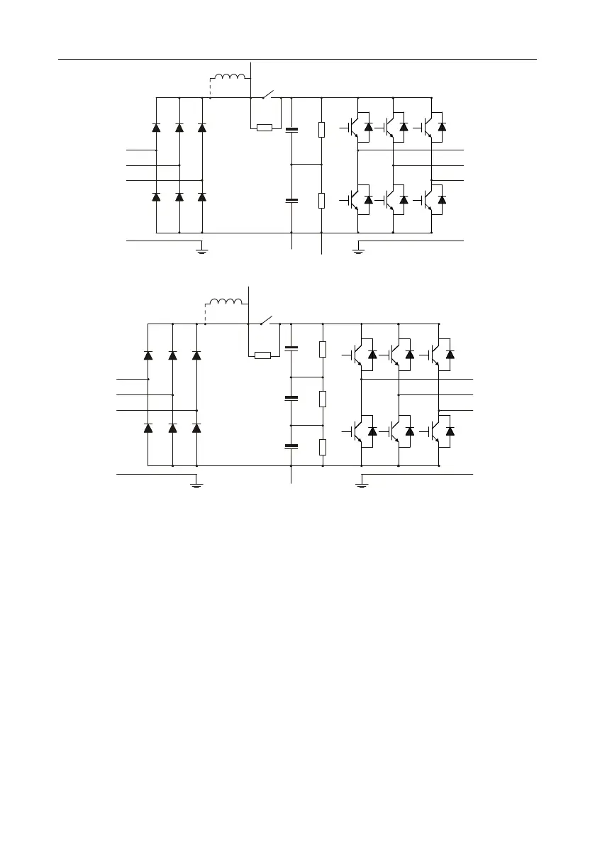
Fig 3.3 380V (132kW and above ) main circuit diagram
R
S
T
U
V
W
(+)
(-)
DC reactor
P1
PE PE
Fig 3.4 660V main circuit diagram
Note:
1. 132kW and above inverters can be connected to external DC reactors. Before connection, it is
required to take off the copper bar between P1 and (+). 132kW and above inverters can be
connected to external brake unit. DC reactors and brake units are optional parts.
2. 18.5kW–110kW (inclusive) inverters are equipped with built-in DC reactor.
3. 37kW and below models carry built-in brake units, 45kW–110kW (inclusive) supports built-in
brake unit. The models that carry built-in brake unit can also be connected to external brake
resistor. The brake resistor is optional part.
4. 660V inverters can be connected to external DC reactor. Before connection, it is required to take
off the copper bar between P1 and (+). 660V inverters can be connected to external brake unit.
DC reactors and brake units are optional parts.
 Loading...

