Goodrive350 series high-performance multi-function inverter Chapter 4
-30-
within 25m;
3. H1 and H2 terminals are short connected to +24V by default;
it is required to remove the short-contact tag on the terminal before
using STO function.
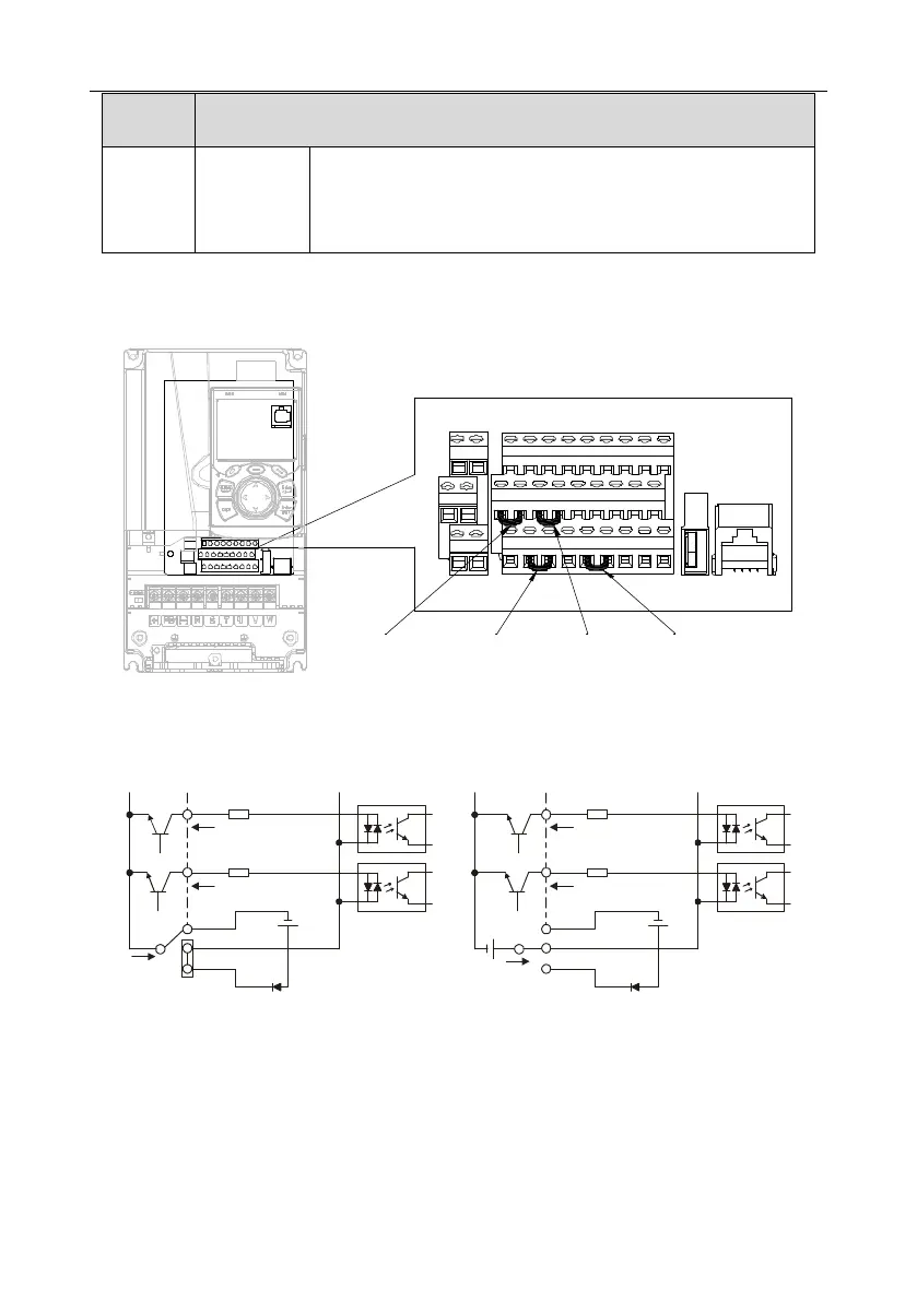
4.4.2 Input/output signal connection diagram
Set NPN /PNP mode and internal/external power via U-type short-contact tag. NPN internal mode is
adopted by default.
U-type short-
contact tag of H2
and +24V
U-type short-contact
tag of COM and
+CME
U-type short-
contact tag of
+24V and PW
U-type short-
contact tag of H1
and +24V
+24V
485++24V CME 485-485GCOMCOMPE H2
R01CR02C
H1 +24V
R01BR02B
PW COM HDO Y1 AO1 GND
S1 S2 S3 S4 HDIA HDIB AI1 AI2 +10V
R01AR02A
Fig 4.19 Position of U-type short-contact tag
If input signal comes from NPN transistors, set the U-type short-contact tag between +24V and PW
based on the power used according to the figure below.
S1
S2
COM
PW
+
24V
COM
+ 24V
Internal power(NPN mode)
S1
S2
COM
PW
+ 24V
COM
+
24V
External power(NPN mode)
+ 24V
Fig 4.20 NPN mode
If input signal comes from PNP transistor, set the U-type short-contact tag based on the power used
according to the figure below.
 Loading...

