Rev. 2.0
Maintenance Guide
2-10
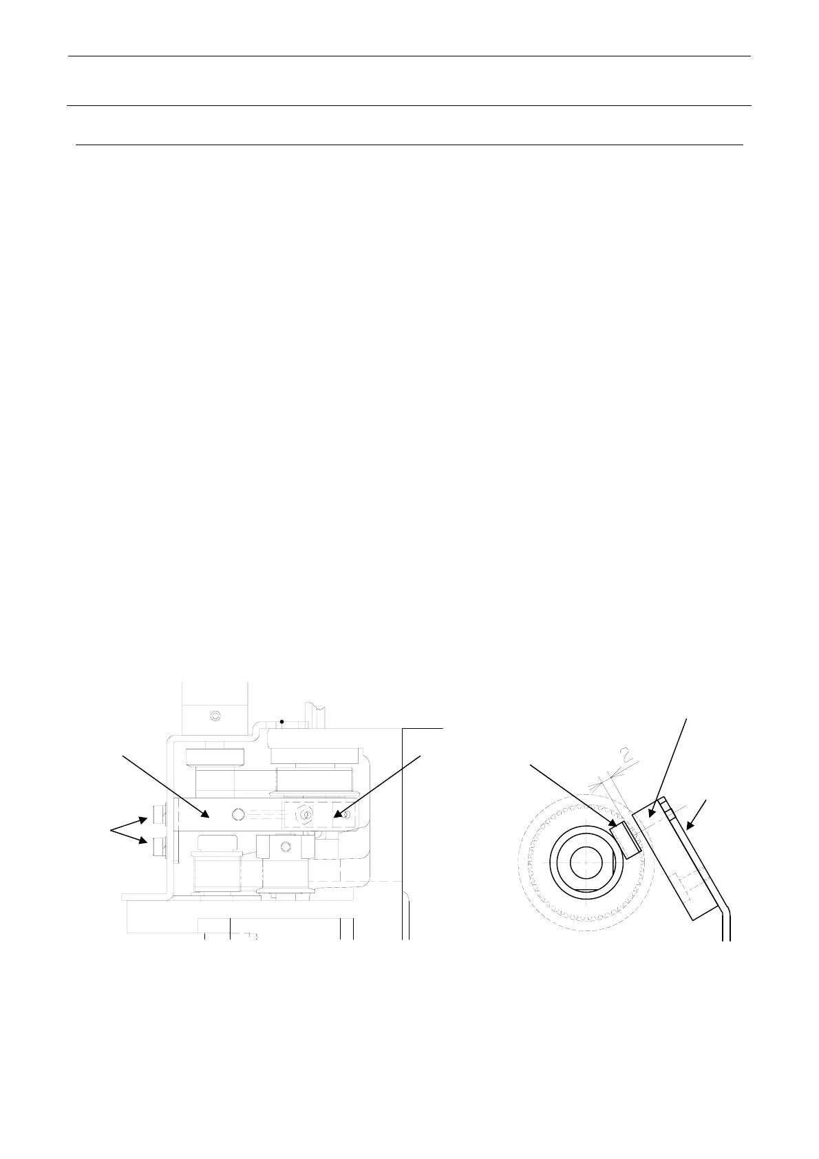
2-3. Replacing the T-Sensor
After the T-sensor has been replaced, perform the home position return to check that it functions
correctly. (For details about input items, see section 2-8.)
1) Detach the T-sensor bracket from the head.
2) Remove the mounting screws d (2 pcs.) of the T-sensor bracket and detach the bracket.
3) Cut the tie-up band securing the T-sensor cables.
4) Remove the T-sensor e from the bracket and replace it.
5) Reassemble the components in the reverse order of disassembly.
∗ Apply Loctite 242 to the mounting screws e and tighten them with a tightening torque of
0.14 N⋅m.
∗ Make the adjustment so that the end face of the motor shaft is aligned with the end face of
the pulley, and then fix the setscrews of the T-pulley.
6) Check following the procedure below and make adjustments if necessary.
<Procedure>
c Make the adjustment so that the clearance between the T-sensor e and T-sensor dog f is 2
mm or less and that the T-sensor is not in contact with other part around it, such as pulley.
d Manually rotate the θ-axis to make sure that the T-sensor is not in contact with the T-sensor
dog.
e Put the servo in the free status with the power to the machine turned ON and manually rotate
the θ-axis to make sure that the sensor is turned ON or OFF if the sensor gets close to the
dog.
d
c
e
e
f
c
Figure 2-3-1

 Loading...


