Rev. 1.0
Maintenance Guide
3-1
DANGER
To prevent any trouble caused by accidental machine start, always
shut-down the power before starting the maintenance and
adjustment work.
[3] PARTS AROUND THE HEAD
3-1. Replacing the Solenoid Valve Components
Before replacing the solenoid valves, always shut-down the main compressed air.
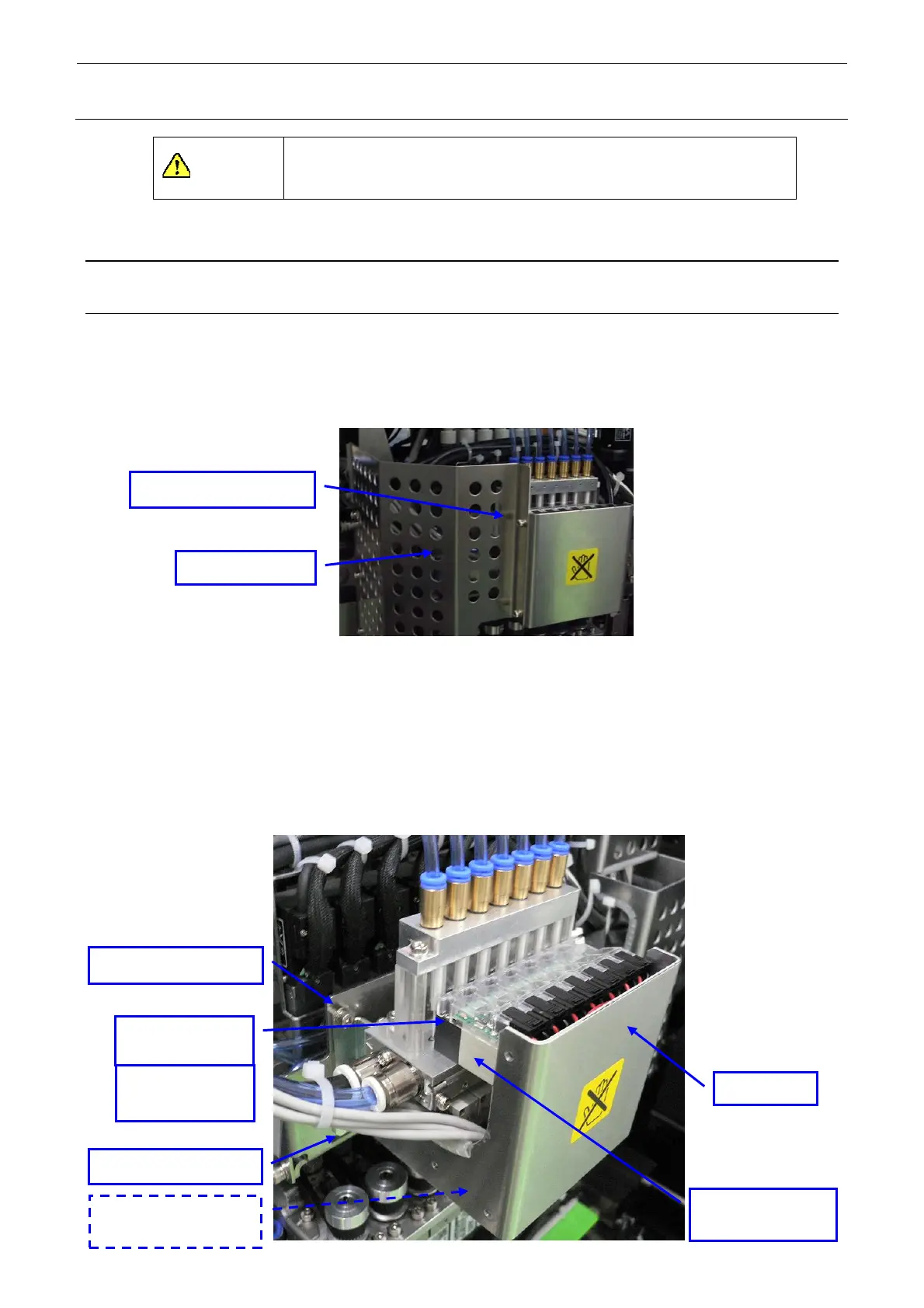
3-1-1. Replacing the Solenoid Valves
1) Remove the SEMS cap bolts c (×2) to detach the head left cover.
c SEMS cap bolt (
5)
Head left cover
2) Remove the SEMS cap bolts d (×4) to detach the head cover.
3) Remove the SEMS cap bolts e (×4), and disconnect the cables and air tubes to detach the
solenoid valve main unit.
4) Remove the round head screws f (×2) to detach each solenoid valve. (Great care should be
taken so that the gasket on the back of the solenoid valve is not lost.)
5) Reassemble the parts and components in the reverse order of disassembly.
6) After the solenoid valves have been replaced, check the solenoid valves through the head
vacuum and the blow ON/OFF of the manual control.
∗ Round head screws f (2 pcs.) and gasket (1 pc.) are accessory parts supplied with each
solenoid valve.
Tightening torque:
0.15±0.02 N⋅m
e SEMS cap bolt (×4)
d SEMS cap bolt (×4)
Head cover
f Round head
screw
×2
Solenoid valve for
vacuum break
Solenoid valve for
vacuum generation

 Loading...


